AI technical title is built by Patsnap AI team. It summarizes the technical point description of the patent document.
A laser scanning device and multi-beam technology, applied in optics, optical components, lenses, etc., can solve problems such as increased waiting time, increased components and assembly work processes, and long time-consuming polygon mirrors.
Inactive Publication Date: 2009-03-18
E PIN OPTICAL IND
View PDF20 Cites 0 Cited by
Summary
Abstract
Description
Claims
Application Information
AI Technical Summary
This helps you quickly interpret patents by identifying the three key elements:
Problems solved by technology
Method used
Benefits of technology
Problems solved by technology
[0004] (2) The polygonal mirror must have the function of high rotation (such as 40,000 rpm), and the precision requirements are high. As a result, the Y-axis width of the reflective surface on the general polygonal mirror is extremely thin, so a cylinder must be added to the conventional LSU. Cylindrical lens so that the laser beam can be focused into a line (a point on the Y-axis) through the cylindrical lens and then projected on the reflector of the polygonal mirror, resulting in increased components and assembly processes
[0005] (3) The conventional multi-faceted mirror must be rotated at a high speed (such as 40000 rpm), resulting in a relatively high rotation noise, and it takes a long time for the multi-faceted mirror to be activated to the working speed, which increases the waiting time after starting up
[0006] (4) In the assembly structure of the conventional LSU, the central axis of the laser beam projected to the polygonal mirror is not directly facing the central rotation axis of the polygonal mirror, so when designing the matching F-θ lens, the off-axis of the polygonal mirror must be considered at the same time The deviation problem (deviation) relatively increases the design and production troubles of the F-θ lens
[0007] Also, the laser scanning device LSU module used by the color printer LBP must simultaneously control the reflection directions of multiple (such as 4) laser beams to simultaneously meet the requirements of linear scanning, such as US patents US6,798,820, US 6,839,074, US 6,914,705, and The laser scanning device LSU module used in the above-mentioned US patent still uses a high-speed rotating polygonal mirror to control the reflection direction of multiple laser beams, which not only has the lack of the above-mentioned conventional laser scanning device LSU, but also has a more complicated structure and configuration This will not only increase the design difficulty, but also relatively increase the volume of the color printer, which does not meet the requirements of thinness and shortness
Method used
Image
Click on the blue label to locate the original text in one second.
Reading with bidirectional positioning of images and text.
Examples
Embodiment Construction
[0028] In order to make the present invention more definite and detailed, preferred embodiment is cited hereby and cooperates following figure, structure and technical characterictic thereof of the present invention are described in detail as follows:
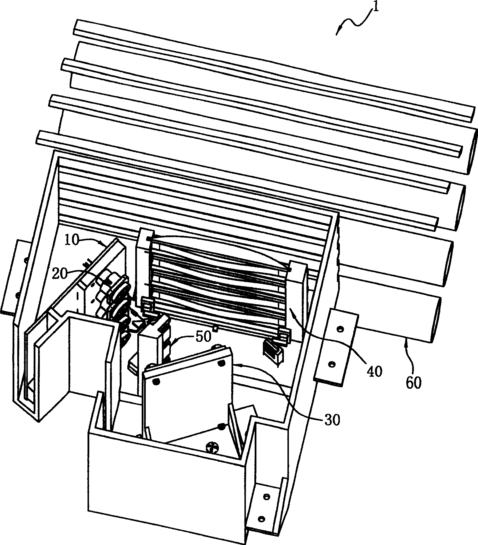
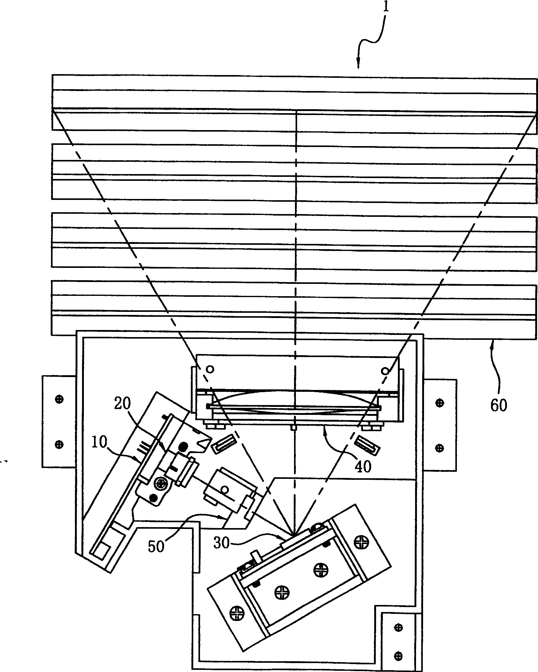
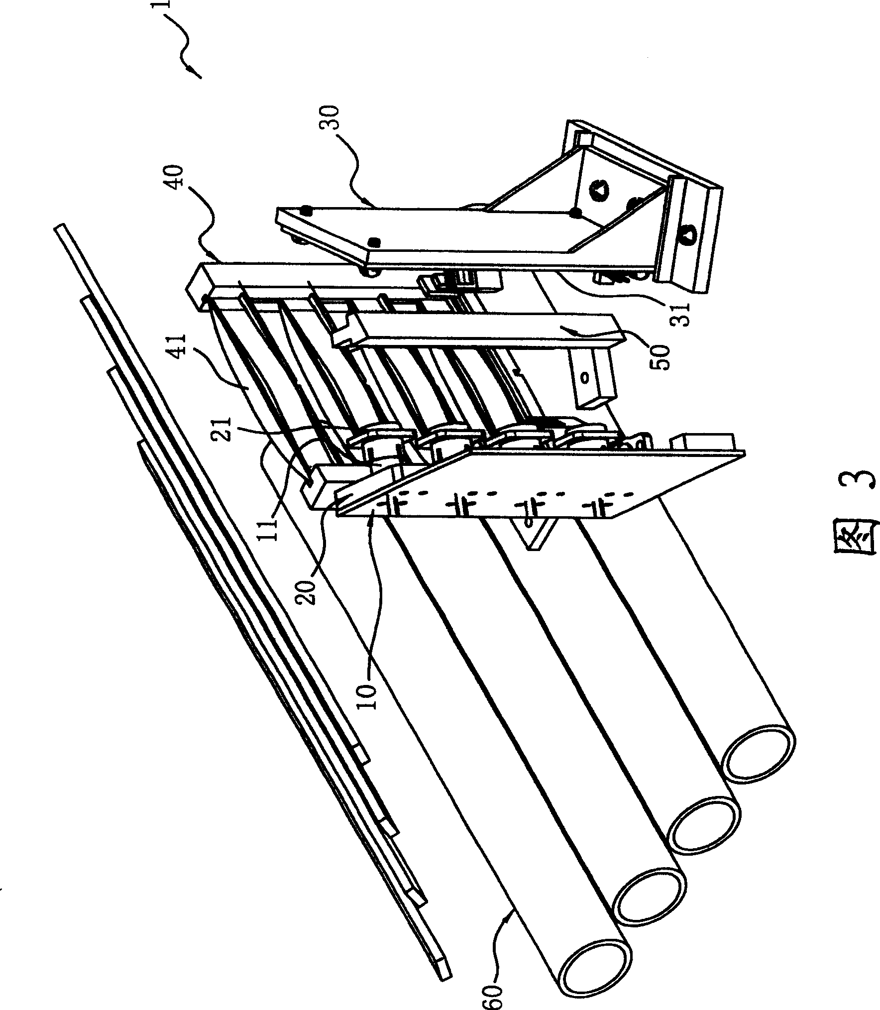
[0029] refer to figure 1 -7, which is a perspective view of a preferred embodiment of the multi-beam in-line laser scanning unit LSU (Multi-Beam Laser Scanning Unit) of the present invention, hereby taking the laser scanning device 1 of four beams as an example, the present invention The in-line LSU1 of multi-beam comprises a semiconductor laser group 10, a collimating lens group 20, a MEMS oscillatory mirror (MEMS oscillatory mirror) group 30, and a linear scanning lens group 40, wherein the semiconductor laser group 10 It can be composed of four groups of single-beam semiconductor lasers LD (single-beam Laser Diode) 11, and each single-beam semiconductor laser 11 emits a laser beam as shown in Figure 9 (A), or two groups of d...
PUM
Abstract
The invention relates to a multi-line laser beam scanning device, which includes a semiconductor laser group, straight-shooting group, a MEMS Swing Mirror Group, and a linear scanning lens group, of which, the semiconductor laser group may shoot multiple laser beam as four beams, respectively the Collimation group formed parallel beam, and each shot to the MEMS Swing Mirror Group, then through the harmonic swing of Mirror Group to linear scanning lens group which respectively reflected from multi-channel laser beam and then by linear scanning lens group enables multi-channel laser beams were projected onto the surface imaging (photosensitive drum), and do the scanning with a uniform velocity rate, and so Laser scanning device achieve the required function of linear scan.
Description
technical field [0001] The present invention provides a multi-beam in-line laser scanning device, especially a micro-electro-mechanical in-line micro-electro-mechanical (MEMS Array) structural type to form a vertically stacked miniaturized in-line MEMS swing mirror group, and utilizes Several F-Sinθ mirrors are stacked vertically to form a linear scanning mirror group corresponding to the in-line mirror group, so as to effectively reduce the size of the color printer and improve scanning efficiency. Background technique [0002] At present, the application technology of LBP (Laser Beam Printer) has included US patents US 5,128,795, US 5,162,938, US 5,329,399, US 5,710,654, US 5,757,533, US 5,619,362, US 5,721,631, US 5,553,729, US 5,911 US6,724,509, and Japan 4-50908, Japan 5-45580 and other patents, and the laser scanning device LSU (Laser Scanning Unit) module used in it mostly uses a high-speed rotating polygon mirror (polygonmirror) to control the laser beam Scanning ac...
Claims
Application Information
Patent Timeline
Application Date:The date an application was filed.
Publication Date:The date a patent or application was officially published.
First Publication Date:The earliest publication date of a patent with the same application number.
Issue Date:Publication date of the patent grant document.
PCT Entry Date:The Entry date of PCT National Phase.
Estimated Expiry Date:The statutory expiry date of a patent right according to the Patent Law, and it is the longest term of protection that the patent right can achieve without the termination of the patent right due to other reasons(Term extension factor has been taken into account ).
Invalid Date:Actual expiry date is based on effective date or publication date of legal transaction data of invalid patent.

