Multibeam straight-line laser scanning device

A scanning device and multi-beam technology, applied in the direction of optics, optical components, lenses, etc., can solve the problems of increased rotation noise, complicated structure and configuration, and long time-consuming polygon mirrors.

Inactive Publication Date: 2007-08-29
E PIN OPTICAL IND
View PDF16 Cites 1 Cited by
  • Summary
  • Abstract
  • Description
  • Claims
  • Application Information

AI Technical Summary

Problems solved by technology

[0004] (2) The polygonal mirror must have the function of high rotation (such as 40,000 rpm), and the precision requirements are high. As a result, the Y-axis width of the reflective surface on the general polygonal mirror is extremely thin, so a cylinder must be added to the conventional LSU. Cylindrical lens so that the laser beam can be focused into a line (a point on the Y-axis) through the cylindrical lens and then projected on the reflector of the polygonal mirror, resulting in increased components and assembly processes
[0005] (3) The conventional multi-faceted mirror must be rotated at a high speed (such as 40000 rpm), resulting in a relatively high rotation noise, and it takes a long time for the multi-faceted mirror to be activated to the working speed, which increases the waiting time after starting up
[0006] (4) In the assembly structure of the conventional LSU, the central axis of the laser beam projected to the polygonal mirror is not directly facing the central rotation axis of the polygonal mirror, so when designing the matching F-θ lens, the off-axis of the polygonal mirror must be considered at the same time The deviation problem (deviation) relatively increases the design and production troubles of the F-θ lens
[0007] Also, the laser scanning device LSU module used by the color printer LBP must simultaneously control the reflection directions of multiple (such as 4) laser beams to simultaneously meet the requirements of linear scanning, such as US patents US6,798,820, US6,839,074, US6, 914,705, and the laser scanning device LSU module used in the above-mentioned U.S. patent still uses a high-speed rotating polygonal mirror to control the reflection direction of multiple laser beams, which not only has the lack of the above-mentioned conventional laser scanning device LSU, but also The structure and configuration are more complicated, which not only increases the difficulty of design, but also relatively increases the volume of the color printer, which does not meet the requirements of thinness and shortness

Method used


Image

  • Multibeam straight-line laser scanning device
  • Multibeam straight-line laser scanning device
  • Multibeam straight-line laser scanning device

Examples


Embodiment Construction

[0028]In order to make the present invention more definite and detailed, preferred embodiment is cited hereby and cooperates following figure, structure and technical characterictic thereof of the present invention are described in detail as follows:

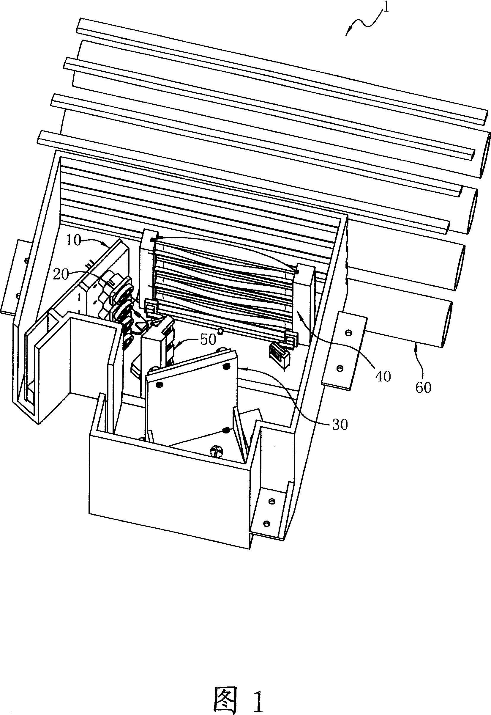
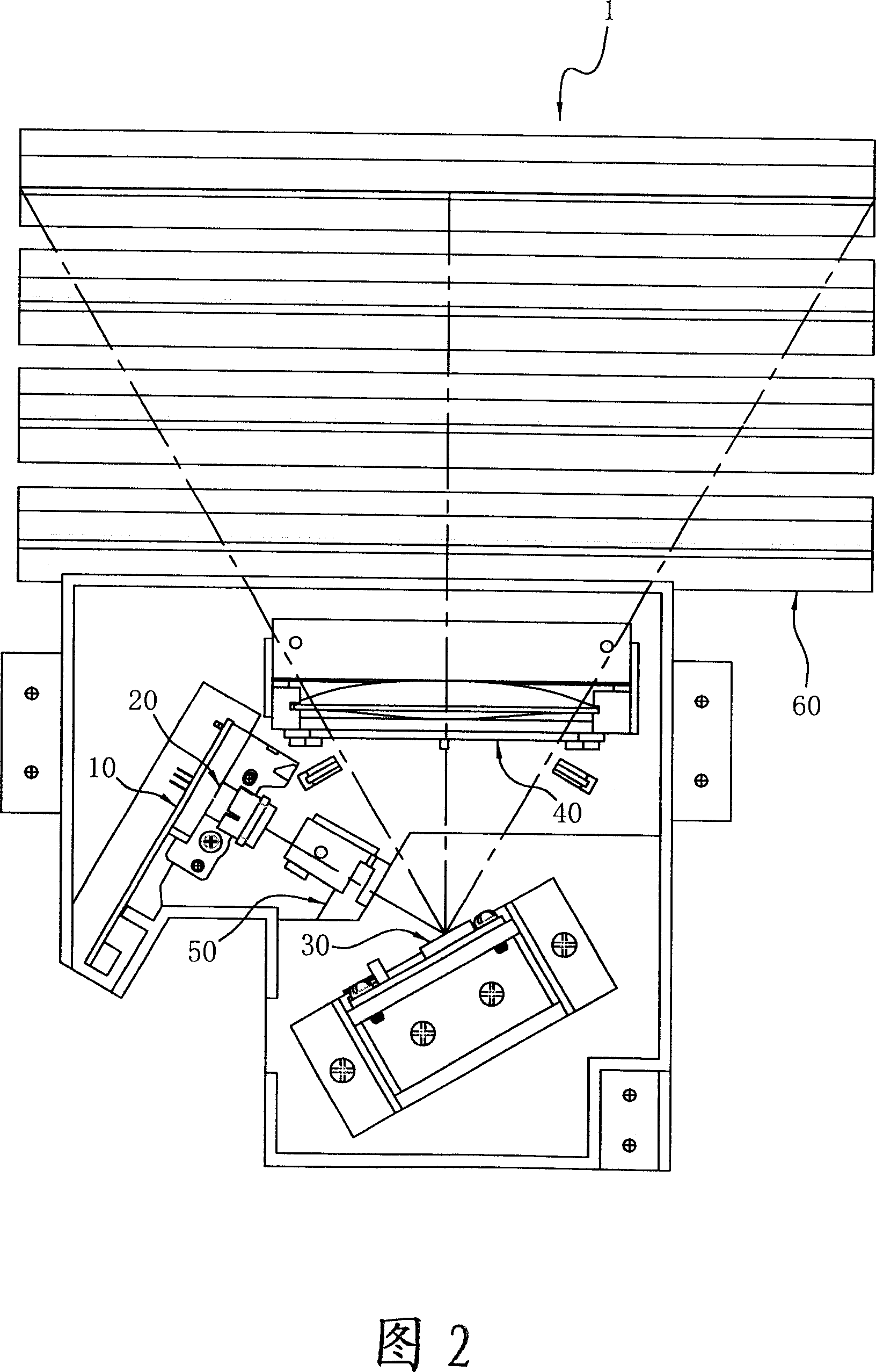
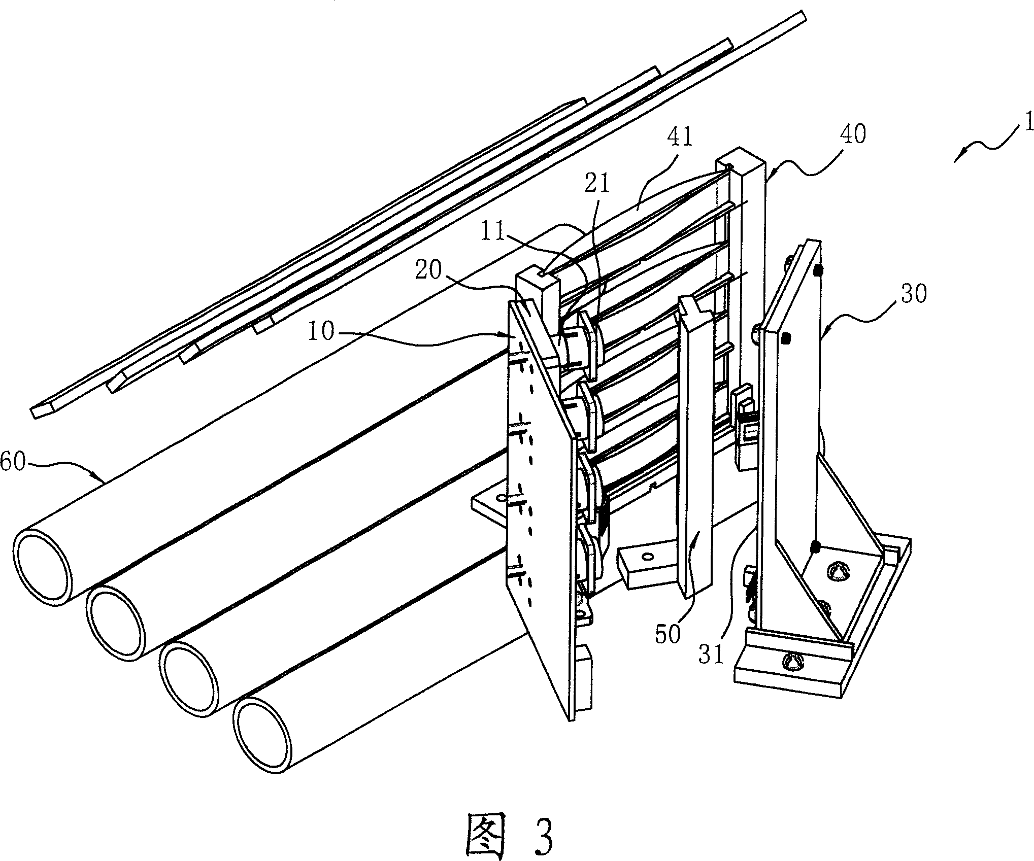
[0029] Referring to Fig. 1-7, it is a three-dimensional schematic diagram of a preferred embodiment of the multi-beam in-line laser scanning unit LSU (Multi-Beam Laser Scanning Unit) of the present invention, hereby the laser scanning device 1 with four beams For example, the multi-beam in-line LSU1 of the present invention includes a semiconductor laser group 10, a collimating mirror group 20, a MEMS oscillatory mirror group 30, and a linear scanning mirror group 40, wherein , the semiconductor laser group 10 can be made up of four groups of single-beam semiconductor laser LD (single-beam Laser Diode) 11, each single-beam semiconductor laser 11 emits a laser beam as shown in Figure 9 (A), or use Two groups of dual-beam semicond...


PUM


Abstract

The invention relates to a multi-line laser beam scanning device, which includes a semiconductor laser group, straight-shooting group, a MEMS Swing Mirror Group, and a linear scanning lens group, of which, the semiconductor laser group may shoot multiple laser beam as four beams, respectively the Collimation group formed parallel beam, and each shot to the MEMS Swing Mirror Group, then through the harmonic swing of Mirror Group to linear scanning lens group which respectively reflected from multi-channel laser beam and then by linear scanning lens group enables multi-channel laser beams were projected onto the surface imaging (photosensitive drum), and do the scanning with a uniform velocity rate, and so Laser scanning device achieve the required function of linear scan.

Description

technical field [0001] The present invention provides a multi-beam in-line laser scanning device, especially a miniaturized in-line MEMS oscillating reflector group formed by using an in-line micro-electromechanical (MEMS Array) structure. Several F-Sinθ mirrors are stacked vertically to form a linear scanning mirror group corresponding to the in-line mirror group, so as to effectively reduce the size of the color printer and improve scanning efficiency. Background technique [0002] At present, the application technology of laser beam printer LBP (Laser Beam Printer) has included US patents US5,128,795, US5,162,938, US5,329,399, US5,710,654, US5,757,533, US5,619,362, US5,721,631, US5, 553,729, US5,111,219, US5,995,131, US6,724,509, and Japan 4-50908, Japan 5-45580 and many other patents, and most of the laser scanning device LSU (Laser Scanning Unit) modules used in them use a high-speed rotating The polygon mirror (polygonmirror) to control the laser beam scanning action ...

Claims


Application Information

Patent Timeline
Patent Type & Authority Applications(China)
IPC IPC(8): G02B26/10G02B3/06
Inventor 徐三伟陈国仁温明华朱翊麟王和彬
Owner E PIN OPTICAL IND
Why Eureka
Try Eureka