
Image processing method, image zone detection method, image processing program, image zone detection program, image processing apparatus and image zone detection apparatus

a technology of image processing and detection method, applied in image watermarking, instruments, television systems, etc., can solve problems such as appearance degradation, and achieve the effect of minimizing visual changes and easy identification

Active Publication Date: 2008-11-20
FUJITSU LTD
View PDF11 Cites 7 Cited by
  • Summary
  • Abstract
  • Description
  • Claims
  • Application Information

AI Technical Summary

Benefits of technology

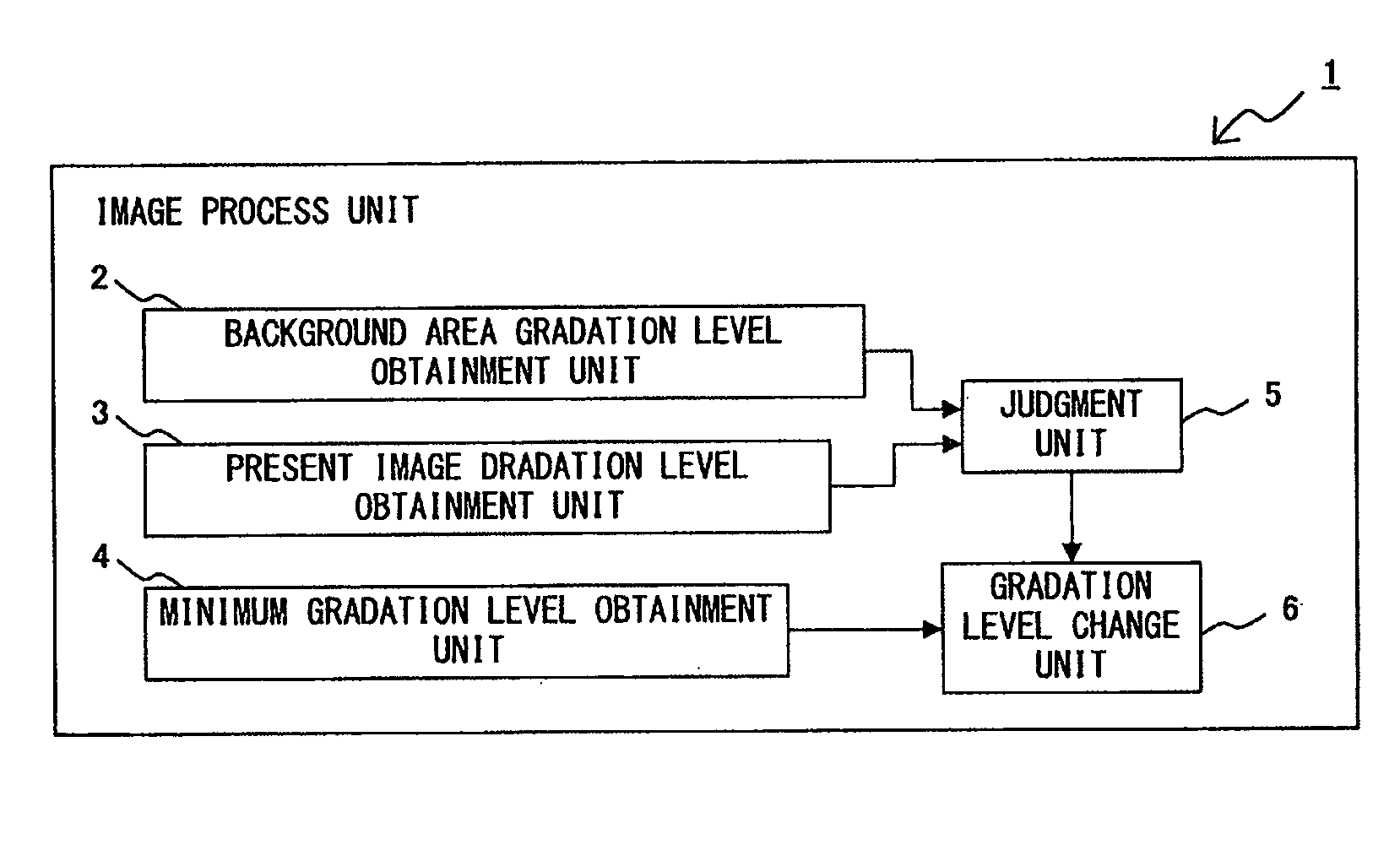
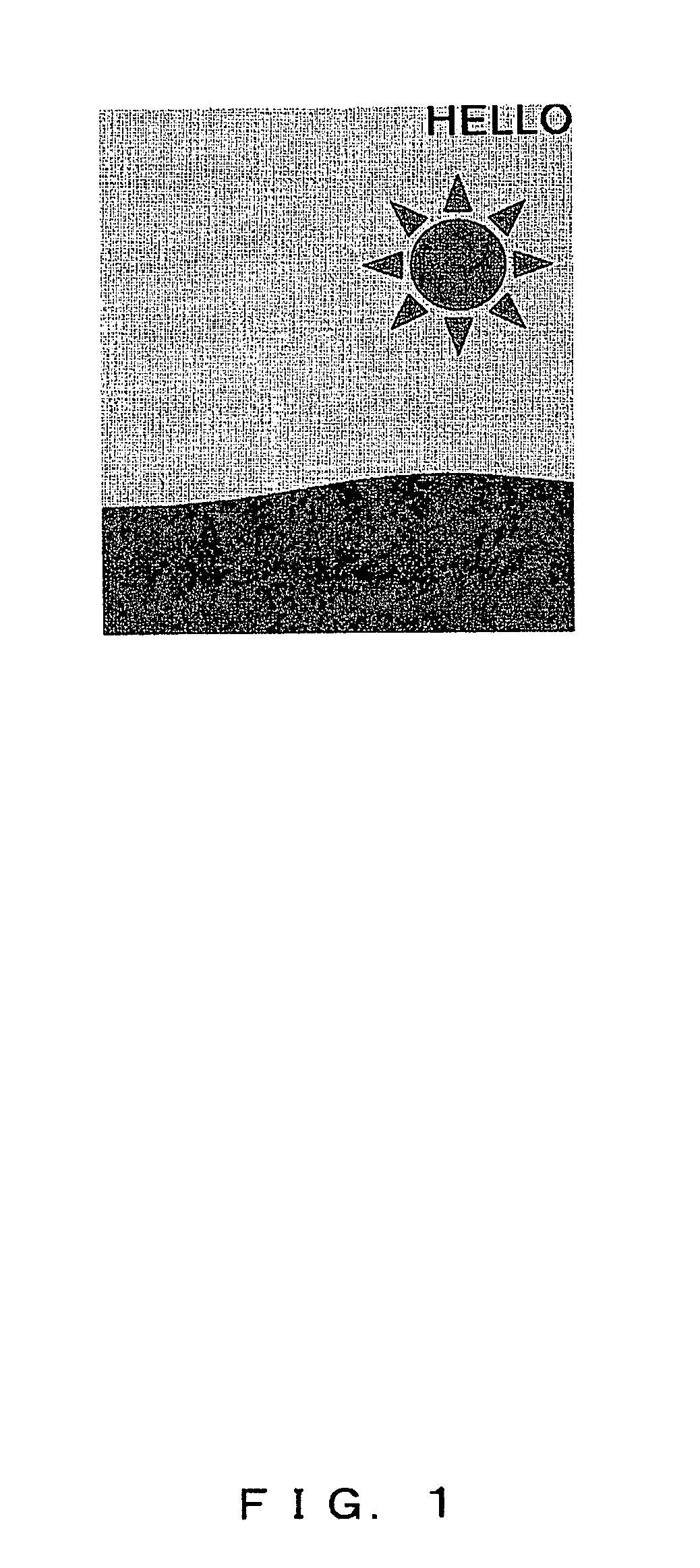
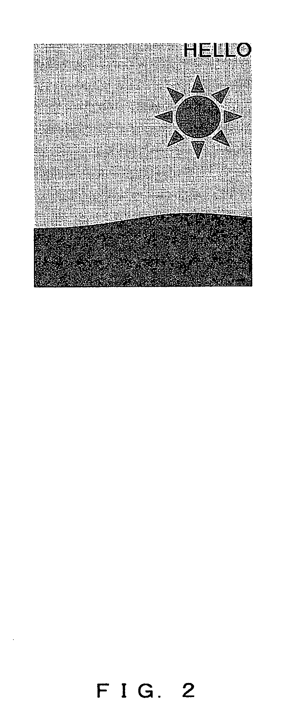
The present invention provides an image processing method for changing the gradation levels of pixels in a rectangular image that contains a code. The method aims to make it easy to identify the four corners of the image. The method involves obtaining the gradation levels of a color that is complementary to yellow for pixels in a background area, and then comparing these levels with the gradation levels of pixels in a target area. The method also involves judging whether the difference between the gradation levels is greater than a threshold value, and if so, changing the gradation level of the pixel to increase the difference from the background area. This change is inconspicuous to the human eye and allows for easy identification of the image zone when the image is printed or displayed electronically.

Problems solved by technology

The conventional techniques are faced with the problem of degrading appearance because the rectangular image is provided with a mark or frame.

Method used


Image

  • Image processing method, image zone detection method, image processing program, image zone detection program, image processing apparatus and image zone detection apparatus
  • Image processing method, image zone detection method, image processing program, image zone detection program, image processing apparatus and image zone detection apparatus
  • Image processing method, image zone detection method, image processing program, image zone detection program, image processing apparatus and image zone detection apparatus

Examples


first embodiment

[0092]The image zone detection unit 11 applies a process for detecting a rectangular zone of an image that is obtained by pictured (i.e., photographing) the rectangular image that is printed on a medium and in which a code is embedded and the gradation levels of a pixel are changed by the method according to the

[0093]As shown in FIG. 8, the image zone detection unit 11 comprises a four-corner assuming unit 12 and a four-corner identification unit 13.

[0094]The four-corner assuming unit 12 assumes the location and size of a section in which one of the four corners of the pictured rectangular image exists.

[0095]The four-corner identification unit 13, comprising a starting point setting unit 14, an edge detection unit 15, a line calculation unit 16, and a corner coordinate determination unit 17. The four-corner identification unit 13 determines a corner coordinate once the unit 13 is initiated. One corner coordinate is determined in one assumed section estimated by the four-corner assum...

second embodiment

[0141]FIG. 18 is a diagram showing the hardware configuration of an apparatus for carrying out an image zone detection process according to the

[0142]The program for carrying out the image zone detection process can be loaded onto RAM (i.e., memory) 43 from a storage apparatus 46 such as ROM 42 and a magnetic disk apparatus and be executed by a CPU 41.

[0143]Alternatively, the program can be loaded onto RAM (i.e., memory) 43 from an external storage apparatus (not shown in a drawing herein) by way of a network and a communication interface 44 and be executed by the CPU 41.

[0144]Further alternatively, the program can be loaded onto the RAM (i.e., memory) 43 from a portable storage medium (not shown in a drawing herein) by way of a media access apparatus 45 and be executed by the CPU 41.

[0145]The user imports a rectangular image printed on a medium or electronically displayed in another medium by using an image pickup apparatus (not shown in a drawing herein). The imported rectangular i...


PUM


Abstract

An image processing method according to the present invention is contrived to change the gradation level (of the color component corresponding to the complementary color of yellow) for a pixel within a zone located on a corner of a rectangular image so as to maximize the difference between the gradation level of a pixel that is a processing target and the gradation level of a pixel in a background area in the surrounding area of the pixel that is the processing target, that is, lowering the gradation level. This means the pixel that is a result of applying the process for changing the gradation levels looks yellowish. The human eye has difficulty in recognizing yellow and therefore the change applied to the pixel is inconspicuous as compared to the case of placing a mark or frame on the outside of a rectangular zone.

Description

BACKGROUND OF THE INVENTION [0001]1. Field of the Invention[0002]The present invention relates to a technique for identifying the four corners of a rectangular image in which a code is embedded when the image is pictured and imported.[0003]2. Description of the Related Art[0004]Conventionally, a rectangular image in which a code is embedded (simply noted as “rectangular image” hereinafter) is printed, or electronically displayed, on a medium, then the image is imported by photographing the rectangular image on the medium with a portable phone equipped with a camera (noted as “camera phone” hereinafter), the code, which is embedded in the rectangular zone using an electronic watermarking technique, is read and the information corresponding to the code is displayed on the screen of the portable phone.[0005]In such a process, a frame is provided on the outside of the rectangular zone, or a mark is provided therein, in order to identify the section in which the imported rectangular zone...

Claims


Application Information

Patent Timeline
Patent Type & Authority Applications(United States)
IPC IPC(8): G06K9/34
CPCG06T1/005G06T2201/0065H04N1/32309H04N5/913H04N1/387
Inventor SUZUKI, GENTASAKAI, KENICHIROCHIBA, HIROTAKA
Owner FUJITSU LTD
Learn More