Fan impeller

a technology of fan and impeller, which is applied in the direction of piston pumps, vessel construction, marine propulsion, etc., can solve the problems of low air pressure, quiet operation, and comparatively bulky

Inactive Publication Date: 2008-11-20
KURZ KASCH
View PDF5 Cites 136 Cited by
  • Summary
  • Abstract
  • Description
  • Claims
  • Application Information

AI Technical Summary

Problems solved by technology

Cross flow fans give off an even airflow along the entire width of the fan, and ...

Method used


Image

  • Fan impeller
  • Fan impeller
  • Fan impeller

Examples


Embodiment Construction

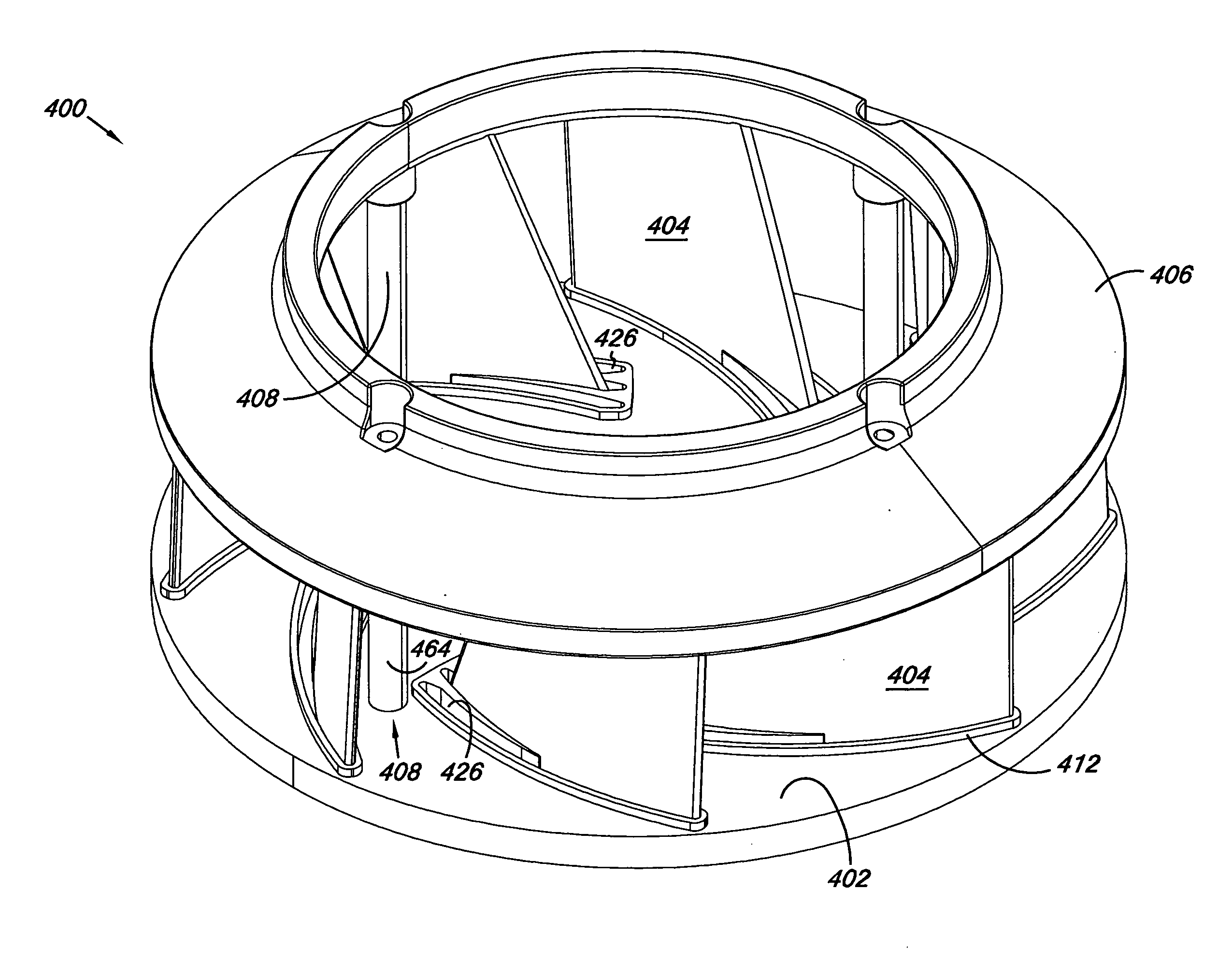
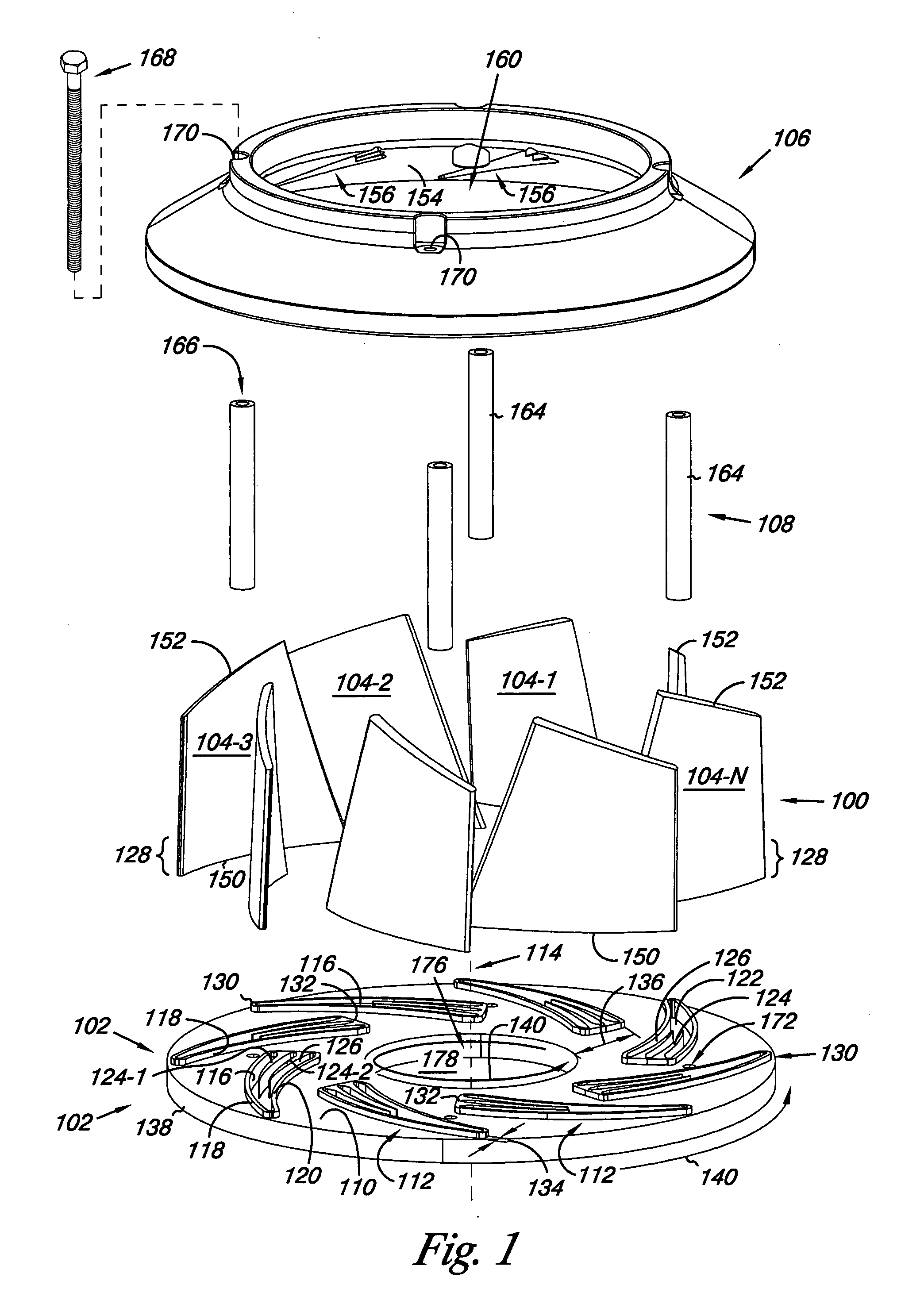
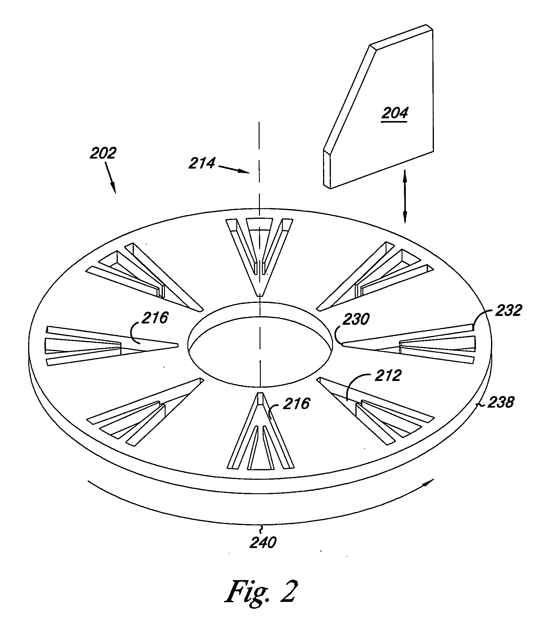
[0013]Embodiments of the present disclosure include impellers, components of impellers, methods of configuring and forming impellers, and fans that include impellers of the present disclosure. As used herein, impellers include, but are not limited to, a rotating device that can be used to move a fluid in a desired direction under a pressure. Fluids can include, but are not limited to, gases and / or liquids. It will be apparent to those skilled in the art that the following description of the various embodiments of this disclosure are provided for illustration only and not for the purpose of limiting the invention as defined by the appended claims and their equivalents.

[0014]The Figures herein follow a numbering convention in which the first digit or digits correspond to the drawing figure number and the remaining digits identify an element in the drawing. Similar elements between different figures may be identified by the use of similar digits. For example, 102 may reference element ...


PUM

PropertyMeasurementUnit
Angleaaaaaaaaaa
Distanceaaaaaaaaaa

Abstract

A fan impeller having fan blades, a base plate, a support ring and fasteners to releasably hold the fan blades between the base plate and the support ring. The base a plate includes channels each having two or more sockets that receive and releasably seat at least a portion of the fan blade. The position of the fan blade relative the axis of rotation of the impeller can be selected from the two or more sockets. The support ring includes grooves in which at least a portion of the fan blade releasably seats to hold the fan blades static relative the base plate and the support ring. The fasteners can extend between the base plate and the support ring to releasably hold the two or more blades.

Description

INTRODUCTION[0001]A fan is a device used to induce airflow and generally made from broad, flat surfaces which revolve or oscillate. The most common applications of fans are for ventilation and / or gas transport for industrial purposes.[0002]There are three main types of fans used for moving air, axial, centrifugal (also called radial) and cross flow (also called tangential). The axial-flow fans have blades that force air to move parallel to the shaft about which the blades rotate. Axial fans blow air linearly across the axis of the fan. This is the most commonly used type of fan, and is used in a wide variety of applications, ranging from small cooling fans for electronics to the giant fans used in wind tunnels.[0003]The centrifugal fan has a moving component called an impeller that consists of a central shaft about which a set of blades form a spiral pattern. Centrifugal fans blow air at right angles to the intake of the fan, and spin (centrifugally) the air outwards to the outlet. ...

Claims


Application Information

Patent Timeline
IPC IPC(8): F04B17/03B23P15/00F04D29/34
CPCB23P15/006Y10T29/49316F04D29/626F04D29/282
Inventor PURVINES, STEPHEN H.
Owner KURZ KASCH
Why Eureka
Try Eureka