
Method for selecting implant components

Active Publication Date: 2008-11-20
BIOMET 3I LLC
View PDF99 Cites 70 Cited by
  • Summary
  • Abstract
  • Description
  • Claims
  • Application Information

AI Technical Summary

Benefits of technology

[0010]According to yet another process, a method of verifying a FEA simulation used to select an implant is provided that creates a 3D CAD model of an actual calibration sample. Properties of the actual calibration sample are assigned to the 3D CAD model. The method performs an FEA simulation of placing the implant into the calibration sample on the 3D CAD model to generate FEA simulation data. An actual implant is placed into the actual calibration sample. The method collects measured

Problems solved by technology

The method modifies FEA simulation variables if the act of ascertaining de

Method used


Image

  • Method for selecting implant components
  • Method for selecting implant components
  • Method for selecting implant components

Examples


Embodiment Construction

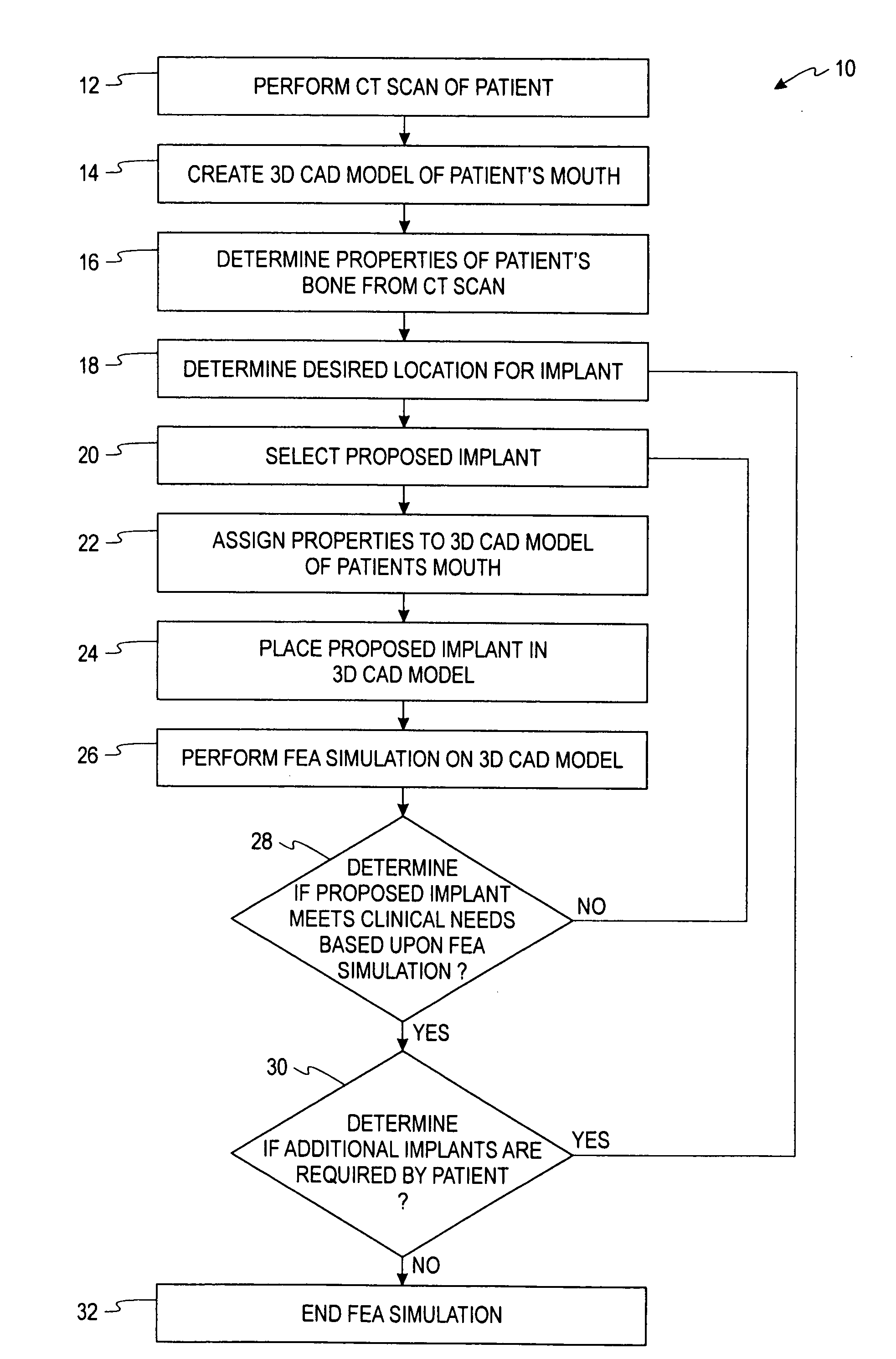
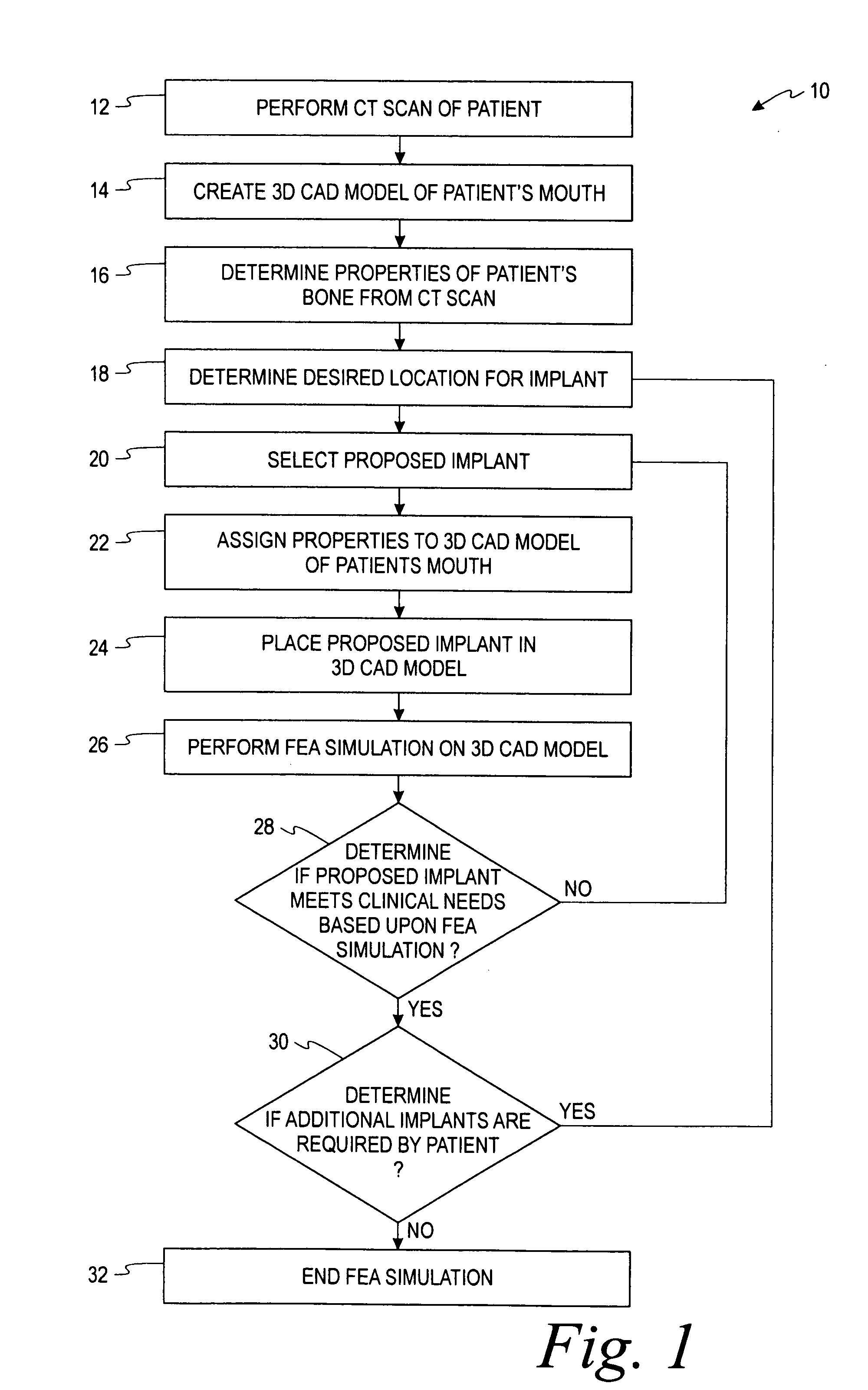
[0017]As shown in FIG. 1 a method 10 is shown to determine initial implant stability. As shown in block 12, a CT scan is performed on a patient. It is contemplated that various types of CT scans may be performed, such as Concentric CT scans or Cone-Beam CT scans. The CT scan produces data that may be used in forming a 3D CAD model of a patient's mouth within a CAD system as depicted in block 14. The CT scan allows a determination to be made regarding the type of bone found in the patient's mandible or maxilla where the implant is to be placed.

[0018]For example, the CT scan allows a practitioner to determine that Type I bone is present, a bone type that has almost all cortical bone tissue. Similarly, the CT scan may reveal that Type II, Type III, or Type IV bone is present at additional different planned implant locations. The various bone types have properties associated therewith, such as Type I bone being harder than Type IV bone. An implant being placed in Type I bone requires ad...


PUM


Abstract

Methods of selecting or designing an implant to be used in a patient are provided. A CT scan of a patient's mouth is performed. A 3D CAD model of the patient's mouth is created utilizing data generated by the CT scan. Properties of the patient's mouth are determined based upon CT scan data and assigned to the 3D CAD model. A desired location for an implant is selected. A FEA simulation is performed on the 3D CAD model to choose an implant or to design an implant that optimizes a selected variable.

Description

RELATED APPLICATIONS[0001]This application is based on U.S. Provisional Application No. 60 / 930,812, filed May 18, 2007, hereby incorporated by reference in its entirety.FIELD OF INVENTION[0002]The present invention relates generally to implant systems for implants placed in bone. More particularly, the present invention relates to restoration components for dental implant systems and a computer model for selecting or developing an implant by optimizing at least one variable utilizing finite element analysis.BACKGROUND OF THE INVENTION[0003]The dental restoration of a partially or wholly edentulous patient with artificial dentition is typically done in two stages. In the first stage, an incision is made through the gingiva to expose the underlying bone. An artificial tooth root, usually a dental implant, is placed in the jawbone for integration. The dental implant generally includes a threaded bore to receive a retaining screw holding mating components therein. During the first stage...

Claims


Application Information

Patent Timeline
IPC IPC(8): A61C13/00
CPCA61C13/0004A61C8/00A61B34/10A61B2034/105A61B2034/108A61B6/032A61B6/14A61B6/505A61C8/009G16H20/40
Inventor BERCKMANS, III, BRUCESUTTIN, ZACHARY B.ROBB, T. TAIT
Owner BIOMET 3I LLC
Features
  • Generate Ideas
  • Intellectual Property
  • Life Sciences
  • Materials
  • Tech Scout
  • Unparalleled Data Quality
  • Higher Quality Content
  • 60% Fewer Hallucinations
Learn More