

Connector
- Summary
- Abstract
- Description
- Claims
- Application Information
AI Technical Summary
Benefits of technology
Problems solved by technology
Method used
Image

Examples
Embodiment Construction
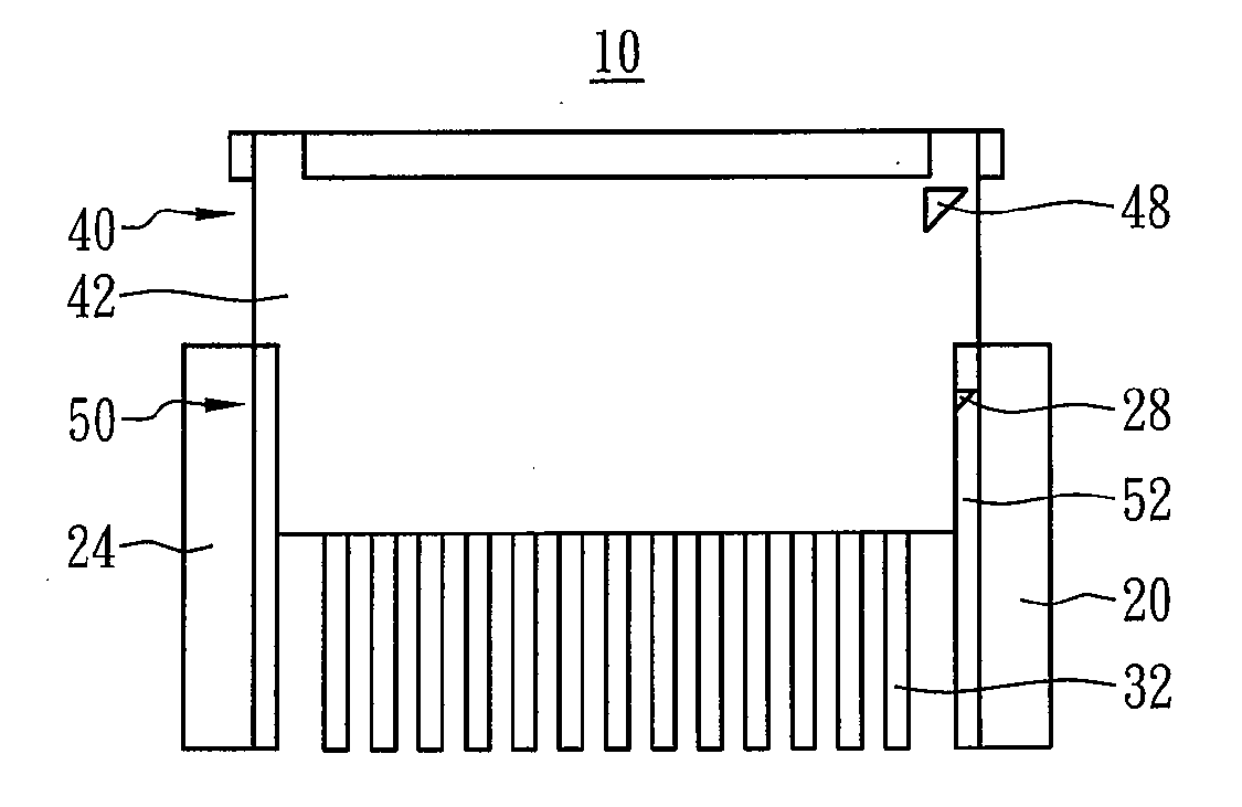
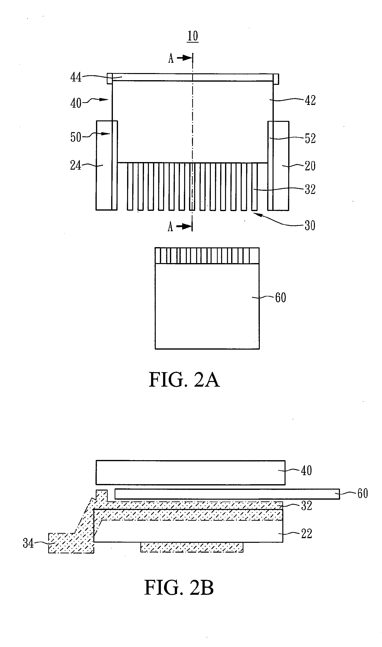
[0016]FIG. 2A schematically illustrates a top view of the connector according to an embodiment of the present invention while FIG. 2B schematically illustrates a cross-sectional view of the connector, taken along line A-A′ in FIG. 2A, according to the present invention. The connector of the present invention can be wildly used in many existing PCBs. It is noted that the size and the shape of the connector shown in the figures of the present invention is used for explanations rather than limiting the scope of the invention.
[0017]According to the embodiment of the present invention, the connector 10 comprises a base 20, at least one first terminal 30, an upper cover 40 and a sliding structure 50. The connector 10 electrically connects to a signal cable 60 wherein the signal cable 60 can be, for example, a flexible printed circuit (FPC), or the like. Specifically, the base 20 comprises a body 22 and two opposite sides 24 configured individually to the two opposite ends of the body 22. ...
PUM
 Abstract
Description
Claims
Application Information