Electrical connector
Inactive Publication Date: 2008-11-20
INARCA
View PDF3 Cites 2 Cited by
Summary
Abstract
Description
Claims
Application Information
AI Technical Summary
This helps you quickly interpret patents by identifying the three key elements:
Problems solved by technology
Method used
Benefits of technology
[0010]The aim of the present invention is to provide an electrical connector which is capable of obviating the drawbacks shown by similar known types of connector.
[0011]Within this aim, an object of the present invention is to provide a connector whose structure allows to protect in the best possible way the integrity of the film hinge and accordingly ensure optimum closure of the cover on the box-like body of the connector.
[0013]Another object of the present invention is to provide an electrical connector which can be manufactured cheaply with known systems and technologies.
Problems solved by technology
If, due to production problems, for example related to the dimensional tolerances of the connector, the contact of the hinge against the curved surface of the edge is not ideal, unwanted situations can occur for the integrity of the hinge and for the functionality of the connector as a whole.
A first unwanted situation can occur if the hinge, when the cover is closed, is placed under tension because it is “shorter” than the extension of the arc of the profile of the curved surface, whereas instead a second inconvenient situation can be caused by the “greater” length of the hinge with respect to the arc; in this case, the cover might be closed with a certain play and therefore may open in case of excessive stresses, which a connector undergoes if, for example, it belongs to an electric motor of a washing machine or of a car or of another device which is subjected to vibrations, jolts, impacts or other similar stresses.
The opening of the cover, either due to breakage of the hinge or due to disengagement caused by loose closure, allows the penetration of dirt into the connector and places at risk the stability of the contact, since the cable, which is normally locked in the connector by the closed cover, is no longer stably retained in its seat.
Method used
Image
Click on the blue label to locate the original text in one second.
Reading with bidirectional positioning of images and text.
Examples
first embodiment
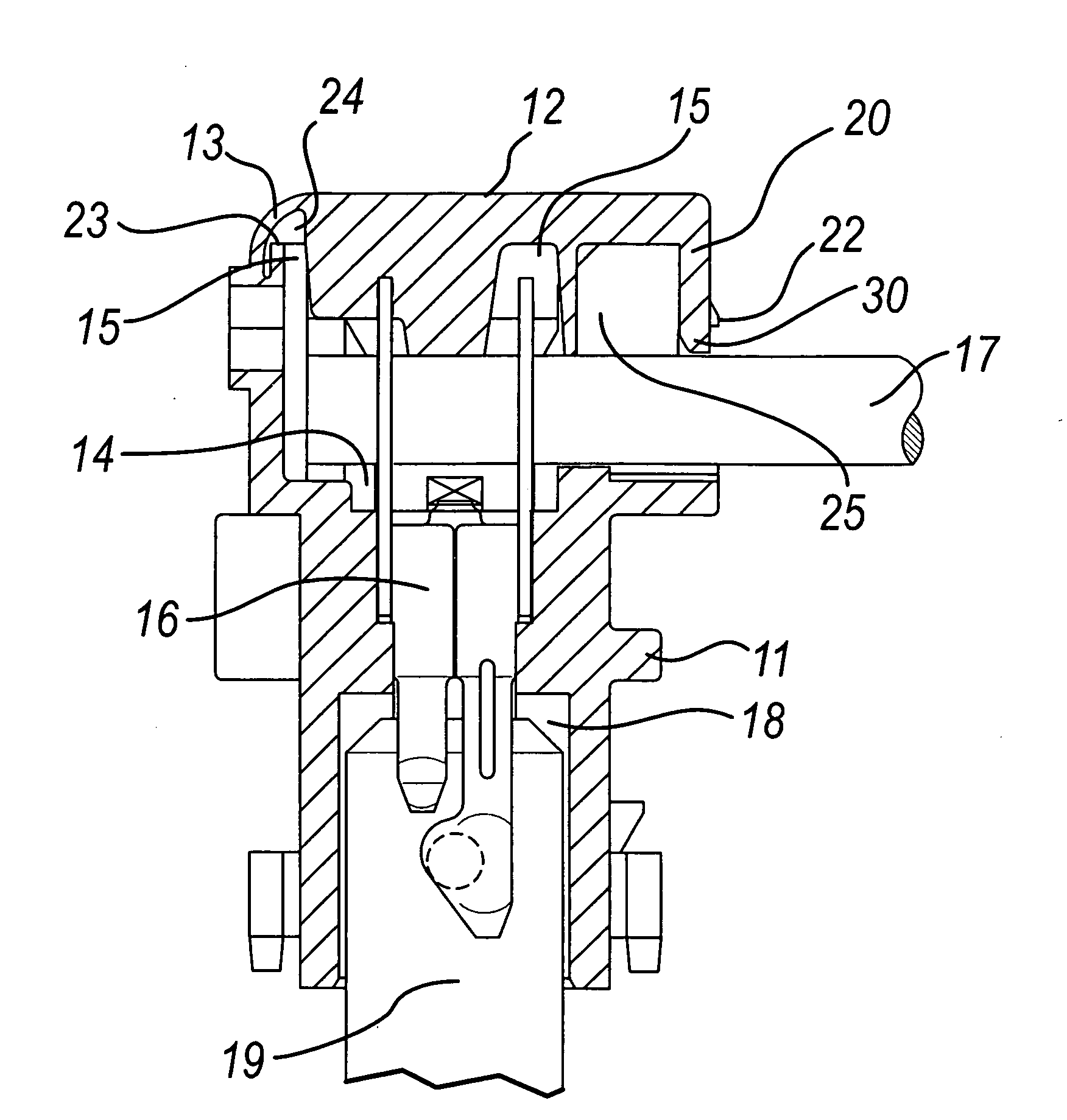
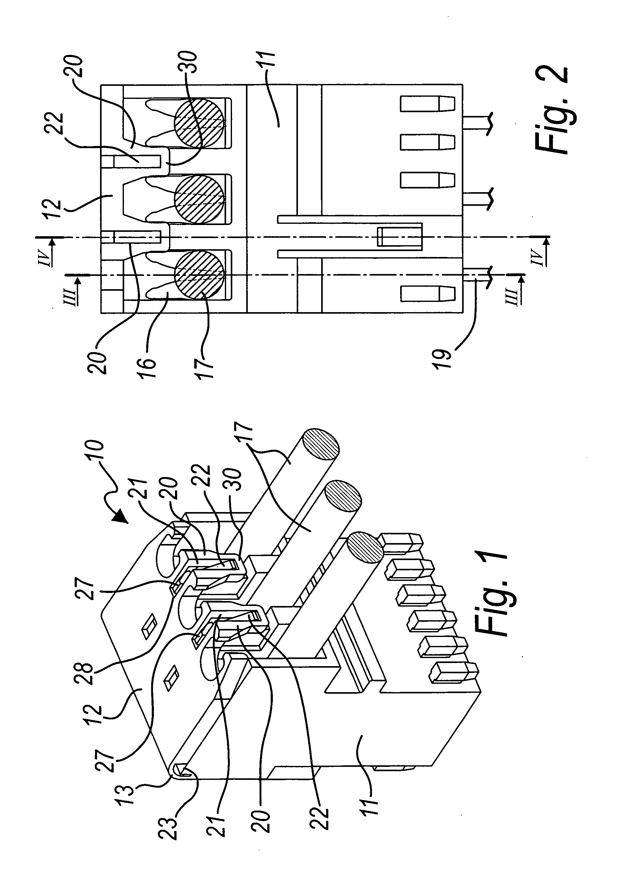
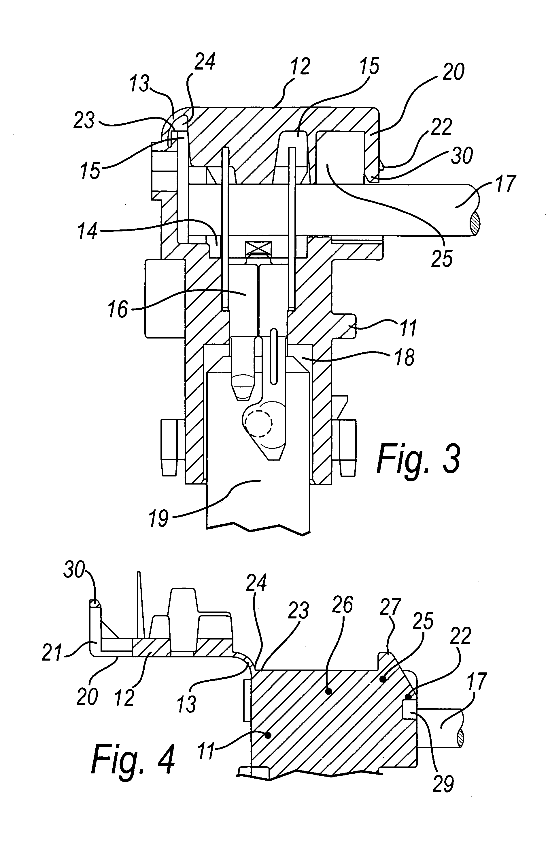
[0022]The connector 10, which is shown in FIGS. 1 to 4, is of the type constituted by a box-like body 11 with a closure cover 12 which is associated therewith by means of a film hinge 13.
[0023]In this embodiment, which is described by way of non-limiting example of the invention, inside the box-like body 11 there are three first seats 14, with an opening 15 for access from the side of the cover 12, for a female electrical terminal 16 for connection of an electrical cable 17.
[0024]Each first seat 14 is matched by a contiguous second seat 18, which is open onto the first seat 14, for a male electrical terminal 19 to be mated with the female terminal 16.
[0025]The free end of the cover 12 is provided with two tabs 20, on each of which there is an engagement slot 21 for a corresponding tooth 22 which protrudes from the box-like body 11.
[0026]A space 24 for the free flexing of the film hinge 13 is formed at the edge 23 of the box-like body 11 located between the film hinge 13 and the open...
second embodiment
[0034]In the invention, which also is an exemplifying embodiment, the connector according to the invention, designated by the reference numeral 110, has a box-like body 111 which is preset to accommodate a single female terminal for the cable 117.
[0035]The cover 112 has two lateral tabs 120 with the slots 121 for two teeth 122.
[0036]The space 124 between the hinge 113 and the cover 112, at the edge 123, is clearly visible.
[0037]In this embodiment, the abutment is provided by a recess 129 which is provided to the rear of the slot 121 and proximate thereto, and a corresponding wider head 127 is inserted in the recess 129.
[0038]The tab 20 and 120 engaged on the corresponding tooth 22 and 122, in cooperation with the wider head 27 and 127 and the corresponding abutment, prevent the cover from being closed with a play which allows opening in case of excessive stresses.
[0039]The connector 10 and 110 according to the invention, thanks to the space 24 and 124 for the movement of the hinge 1...
PUM
Abstract
An electrical connector, of the type constituted by a box-like body with a closure cover which is associated therewith by way of a film hinge and inside which there is at least one first seat, with an opening for access on the part of the cover, for a female electrical connection terminal for an electrical cable and at least one optional contiguous second seat, which is open onto a corresponding first seat, for a male electrical terminal to be mated with the female terminal; at the free end of the cover there is at least one tab in which there is an engagement slot for a corresponding tooth which protrudes from the box-like body. At the edge of the box-like body arranged between the film hinge and the at least one opening for accessing the corresponding first seat there is a space for the free flexing of the film hinge.
Description
[0001]The present invention relates to an electrical connector.BACKGROUND OF THE INVENTION[0002]In order to facilitate and automate the assembly of the electrical connections of the electrical / electronic components of a generic machine or device, connectors for accommodating electrical terminals to be connected to electrical connecting wires are currently used increasingly.[0003]In particular, connecting assemblies thus formed are used in wiring to be mass-manufactured.[0004]These known electrical connectors are constituted generally by a box-like body, which has a closure cover which is associated therewith by means of a film hinge; inside the box-like body there are one or more seats, with access from the cover side, for a corresponding number of female electrical connection terminals for a respective electrical cable, and optional contiguous second seats, which are open onto a corresponding first seat, for male electrical terminals to be mated with the female terminals.[0005]The ...
Claims
Application Information
Patent Timeline
Application Date:The date an application was filed.
Publication Date:The date a patent or application was officially published.
First Publication Date:The earliest publication date of a patent with the same application number.
Issue Date:Publication date of the patent grant document.
PCT Entry Date:The Entry date of PCT National Phase.
Estimated Expiry Date:The statutory expiry date of a patent right according to the Patent Law, and it is the longest term of protection that the patent right can achieve without the termination of the patent right due to other reasons(Term extension factor has been taken into account ).
Invalid Date:Actual expiry date is based on effective date or publication date of legal transaction data of invalid patent.