
Cervical plate locking mechanism and associated surgical method

a technology of cervical plate and locking mechanism, which is applied in the field of cervical plate locking mechanism, can solve the problems of ineffectiveness of many of these locking mechanism, reverse threading or backing out is obviously problematic, and the screw tends to reverse thread, etc., and achieves the effect of simple and inexpensive design, robust, and effective in performan

Active Publication Date: 2008-11-20
CTL MEDICAL CORP
View PDF59 Cites 40 Cited by
  • Summary
  • Abstract
  • Description
  • Claims
  • Application Information

AI Technical Summary

Benefits of technology

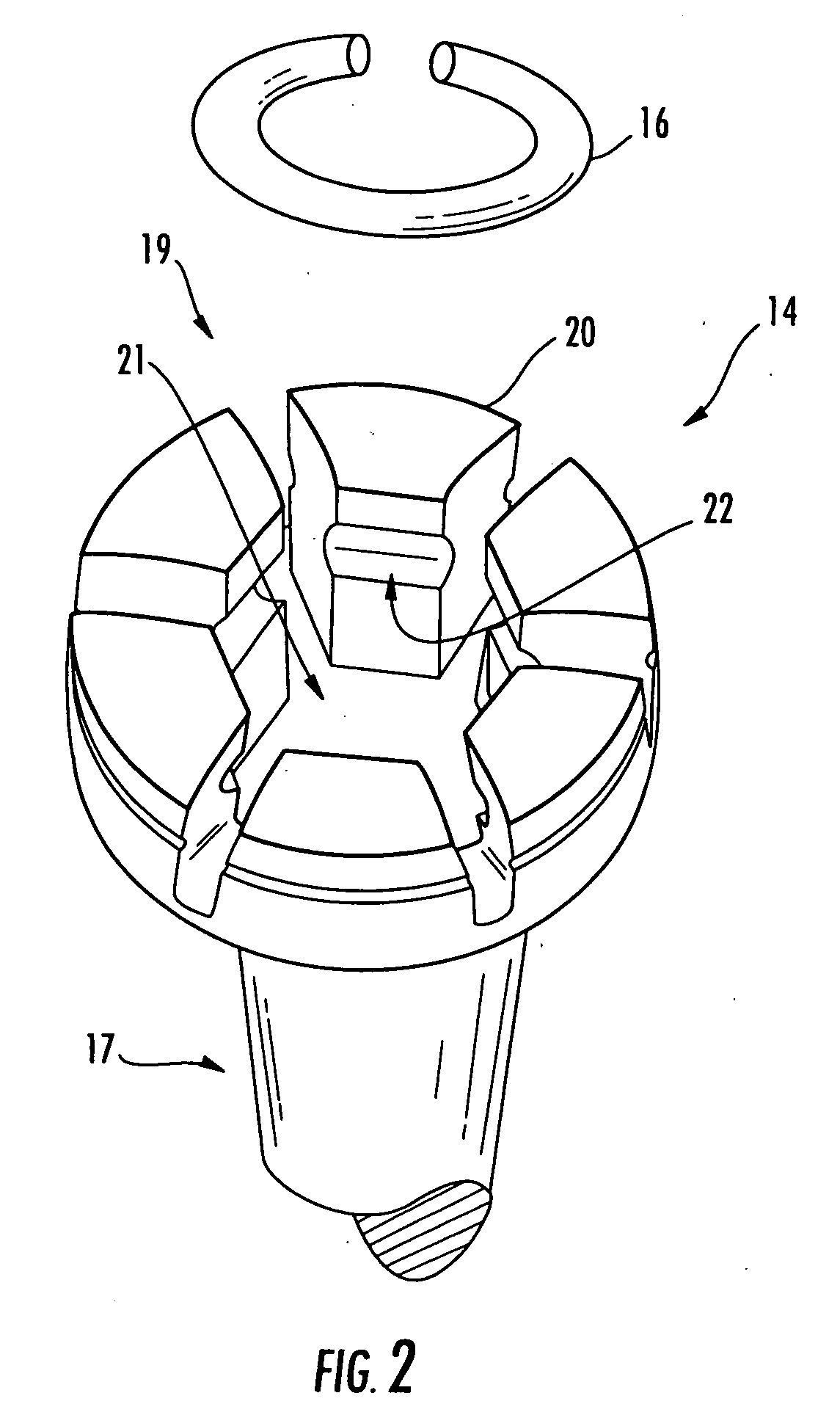
[0004]In various exemplary embodiments, the present invention provides such a robust, simple, and inexpensive cervical plate locking mechanism. The cervical plate locking mechanism of the present invention is elegant in its design and effective in its performance, and utilizes a plate with holes that each incorporate a locking lip structure, or receiving well, and locking screws that each incorporate a head portion having petal structures that are outwardly biased prior to insertion via an internally-disposed c-ring or the like. Advantageously, the lead-in torque of each of the locking screws is less than the lead-out torque of each of the locking screws. Thus, reverse threading or backing out is prevented.

Problems solved by technology

Absent some sort of locking mechanism, these bone screws tend to reverse thread, or back out, over time.
This reverse threading or backing out is obviously problematic.
Many of these locking mechanisms are ineffective, overly complicated, cumbersome to implement, and / or unnecessarily expensive.

Method used


Image

  • Cervical plate locking mechanism and associated surgical method
  • Cervical plate locking mechanism and associated surgical method
  • Cervical plate locking mechanism and associated surgical method

Examples


Embodiment Construction

[0016]As described above, in various exemplary embodiments, the present invention provides a robust, simple, and inexpensive cervical plate locking mechanism. The cervical plate locking mechanism of the present invention is elegant in its design and effective in its performance, and utilizes a plate with holes that each incorporate a locking lip structure, or receiving well, and locking screws that each incorporate a head portion having petal structures that are outwardly biased prior to insertion via an internally-disposed c-ring or the like. Advantageously, the lead-in torque of each of the locking screws is less than the lead-out torque of each of the locking screws. Thus, reverse threading or backing out is prevented.

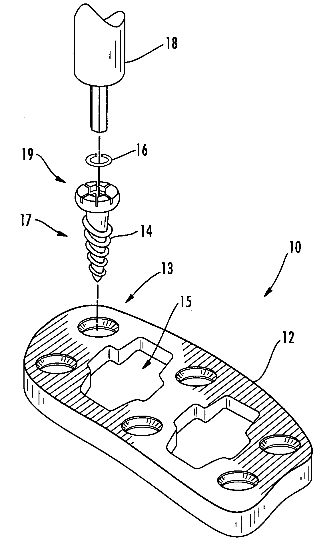
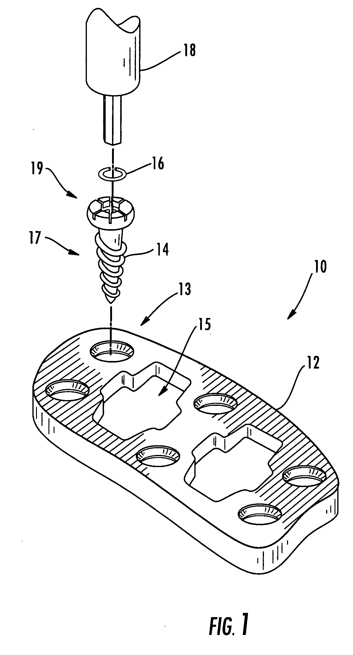
[0017]FIG. 1 is an exploded perspective view of one exemplary embodiment of the cervical plate locking mechanism 10 of the present invention (being installed using a keyed screwdriver 18 or the like), the cervical plate locking mechanism 10 including both novel plat...


PUM


Abstract

The cervical plate locking mechanism of the present invention is elegant in its design and effective in its performance, and utilizes a plate with holes that each incorporate a locking lip structure and locking screws that each incorporate a head portion having petal structures that are outwardly biased prior to insertion via an internally-disposed c-ring or the like. Advantageously, the lead-in torque of each of the locking screws is less than the lead-out torque of each of the locking screws. Thus, reverse threading or backing out is prevented.

Description

FIELD OF THE INVENTION[0001]The present invention relates generally to a cervical plate locking mechanism and an associated surgical method. More specifically, the present invention relates to a cervical plate locking mechanism that includes one or more novel locking screws and a novel plate that works cooperatively therewith. The cervical plate locking mechanism, the one or more novel locking screws, and the novel plate are used for the fixation / stabilization of the cervical spine; alternatively, the fixation / stabilization of the lumbar spine; alternatively, the fixation / stabilization of the sacral spine; the placement of bone grafts, biocompatible inserts, or the like; alternatively, the fixation / stabilization of other anatomical structures; and, alternatively, the fixation / stabilization of other non-anatomical structures.BACKGROUND OF THE INVENTION[0002]The vertebrae of the human spine are generally arranged in a column, with an intervertebral disc disposed between each. These in...

Claims


Application Information

Patent Timeline
IPC IPC(8): A61B17/70A61B17/58
CPCA61B17/7059A61B17/8605A61B17/8038A61B17/8033
Inventor CAWLEY, TRACE
Owner CTL MEDICAL CORP
Learn More