Method and apparatus for monitoring energy consumption of an electronic device

a technology of electronic devices and monitoring methods, applied in the field of electronic devices, can solve problems such as frequency values that are likely to affect performance, system devices can overheat or have reduced battery life,

Inactive Publication Date: 2008-11-20
GLOBALFOUNDRIES INC
View PDF5 Cites 25 Cited by
  • Summary
  • Abstract
  • Description
  • Claims
  • Application Information

AI Technical Summary

Problems solved by technology

System devices can overheat or have reduced battery life when their sub-devices consume more energy than expected.
However, this artificially imposes a frequency value that is likely to affect performance.

Method used


Image

  • Method and apparatus for monitoring energy consumption of an electronic device
  • Method and apparatus for monitoring energy consumption of an electronic device
  • Method and apparatus for monitoring energy consumption of an electronic device

Examples


Embodiment Construction

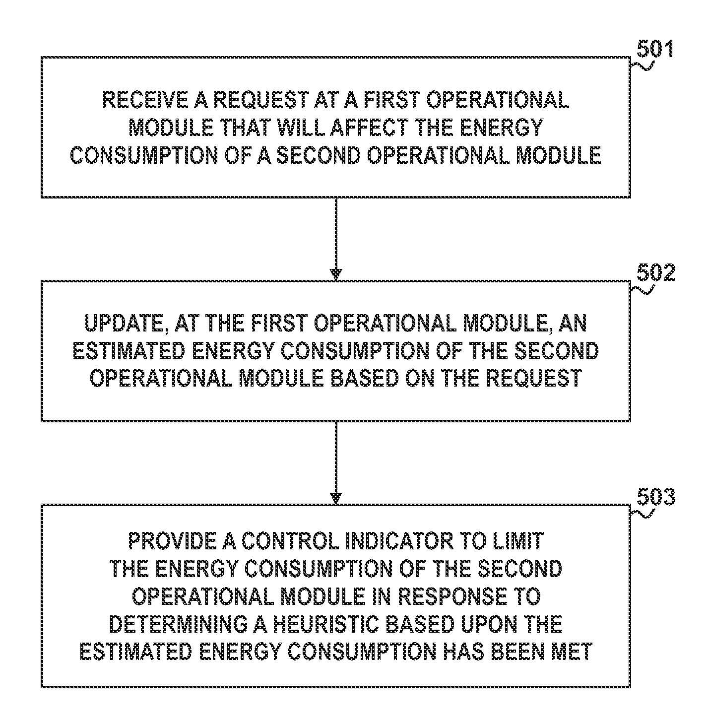
[0013]In accordance with a specific embodiment of the present disclosure, a request is received at a DRAM, wherein an amount of energy will be consumed by the Dram to execute the request. Simultaneously the request is received at a monitoring device where an estimated energy consumption based upon the request is updated. A control indicator is generated by the monitoring device when a heuristic based upon the estimated energy consumption is met. The heuristic can further be based upon energy consumption within a sliding time window. Specific embodiments of the present disclosure will be better understood with reference to FIGS. 1-7.

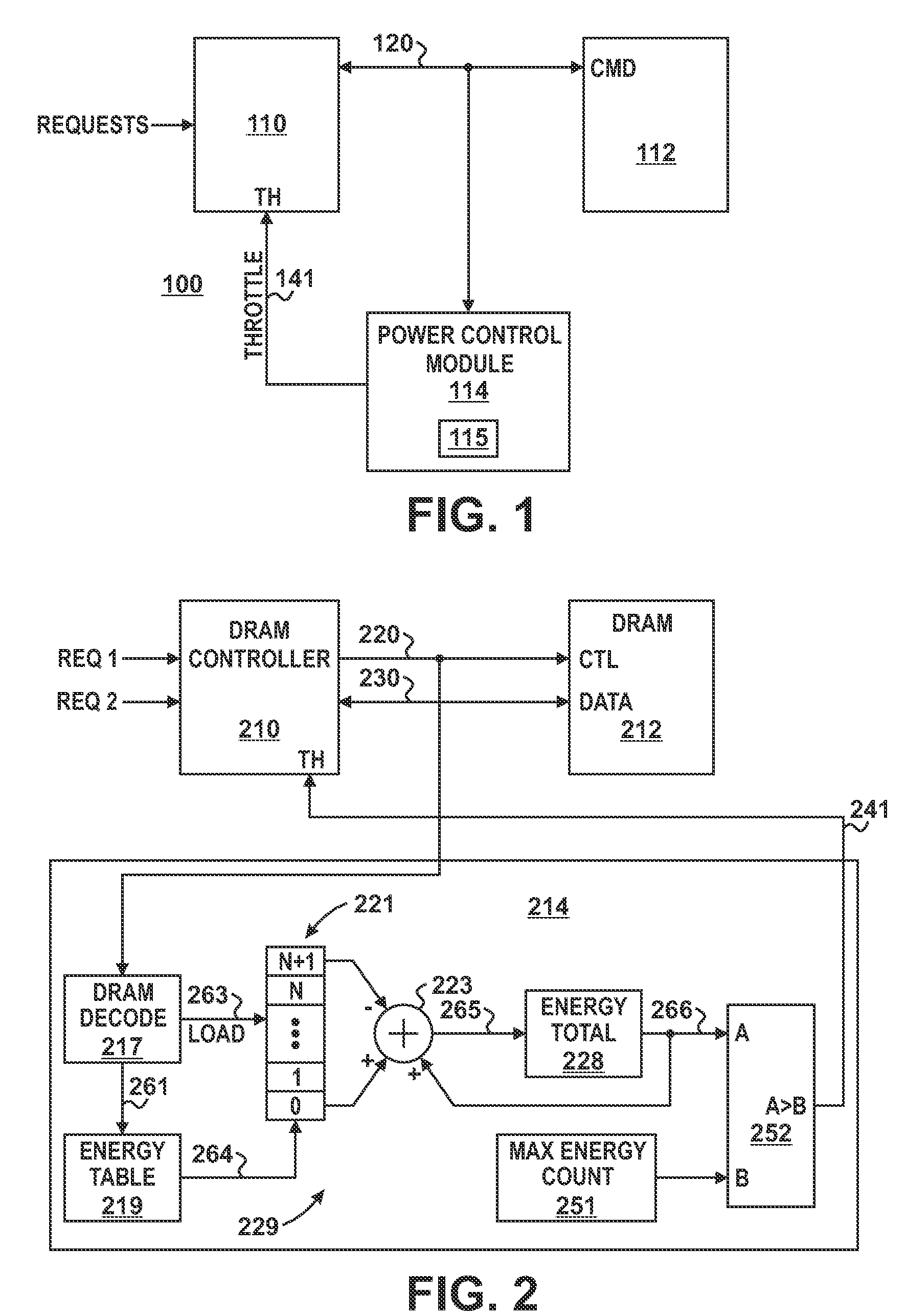
[0014]FIG. 1 illustrates a specific embodiment of a system device 100 that reduces a device's energy consumption if a heuristic based upon the device's energy consumption has been met. System device 100 is illustrated to include a plurality of electronic devices including device 110, device 112, and power control module 114. Device 110 is connected to dev...


PUM


Abstract

Requests to an operational module are received at a monitoring device, where an estimated amount of energy expected to be consumed by the operational module while executing operations related to requests is accumulated for a sliding time window. A throttle signal is generated to limit the amount of energy consumed by the operation module is generated when the accumulated amount exceeds a maximum amount

Description

BACKGROUND[0001]1. Field of the Disclosure[0002]The present disclosure relates generally to electronics, and more particularly to controlling energy consumption of electronic devices.[0003]2. Description of the Related Art[0004]System devices can overheat or have reduced battery life when their sub-devices consume more energy than expected. Various ways of detecting when devices are consuming too much energy have been proposed. For example, a device can shut down or be throttled when a temperature at the device is exceeded. However, this solution does not deterministically limit energy consumption over a number of cycles. Another proposed solution is to set a frequency of a device at a sufficiently low frequency to guarantee the device will not draw more a desired current under any operating condition. However, this artificially imposes a frequency value that is likely to affect performance. Therefore, an apparatus and method of controlling energy consumption of an electronic device...

Claims


Application Information

Patent Timeline
Patent Type & Authority Applications(United States)
IPC IPC(8): G05D3/12
CPCG06F1/3203Y02B60/1228G06F1/3275Y02D10/00
Inventor KRISHNAN, GUHANNUSSBAUM, SEBASTIEN
Owner GLOBALFOUNDRIES INC
Why Eureka
Try Eureka