Method of manufacturing a miniature flexible thrombectomy catheter

a flexible, thrombus catheter technology, applied in the direction of manufacturing tools, catheters, fluid jet surgical cutters, etc., can solve the problems of failure of joint brittleness, low cost of nitinol, etc., to achieve superior pushability and trackability, reduce the effect of nitinol cost and low cos

Active Publication Date: 2008-11-27
BOSTON SCI MEDICAL DEVICE LTD
View PDF85 Cites 14 Cited by
  • Summary
  • Abstract
  • Description
  • Claims
  • Application Information

AI Technical Summary

Benefits of technology

[0007]Another aspect of the forms of the present invention is that cross stream technology is incorporated rather than the other designs used for previous neurologic thrombectomy catheters. Cross stream technology, which uses inflow and outflow windows rather than a circumferential gap, has been shown to have much greater thrombectomy efficacy assuming comparable designs in terms of equivalent vessel safety. Hence, these two approaches of stepping the catheter tube diameter and the use of cross stream technology are the strategies to maximize thrombectomy action of the small profile device.
[0040]A further significant aspect and feature of the present invention is to provide a smaller miniature flexible thrombectomy catheter wherein a guidewire passes through only a portion of the device resulting in less pressure drop along the exhaust passage, and which can also improve the flow of dye through the catheter, thereby increasing catheter performance and procedural performances.

Problems solved by technology

A unique laser swaging process is used to produce a suitable joint to connect the proximal end of the smaller flexible distal high pressure tube having a continuous arcuate fluid jet emanator to the distal end of the flexible nitinol tube which maintains flexibility, whereas prior art jet body devices incorporated welding techniques to join nitinol tubes to stainless steel tubes resulting in joint brittleness which were subject to failure.
Nitinol is not inexpensive, so the jet body uses a proximal high pressure tube of stainless steel for most of the proximal length of the catheter.

Method used


Image

  • Method of manufacturing a miniature flexible thrombectomy catheter
  • Method of manufacturing a miniature flexible thrombectomy catheter
  • Method of manufacturing a miniature flexible thrombectomy catheter

Examples


Embodiment Construction

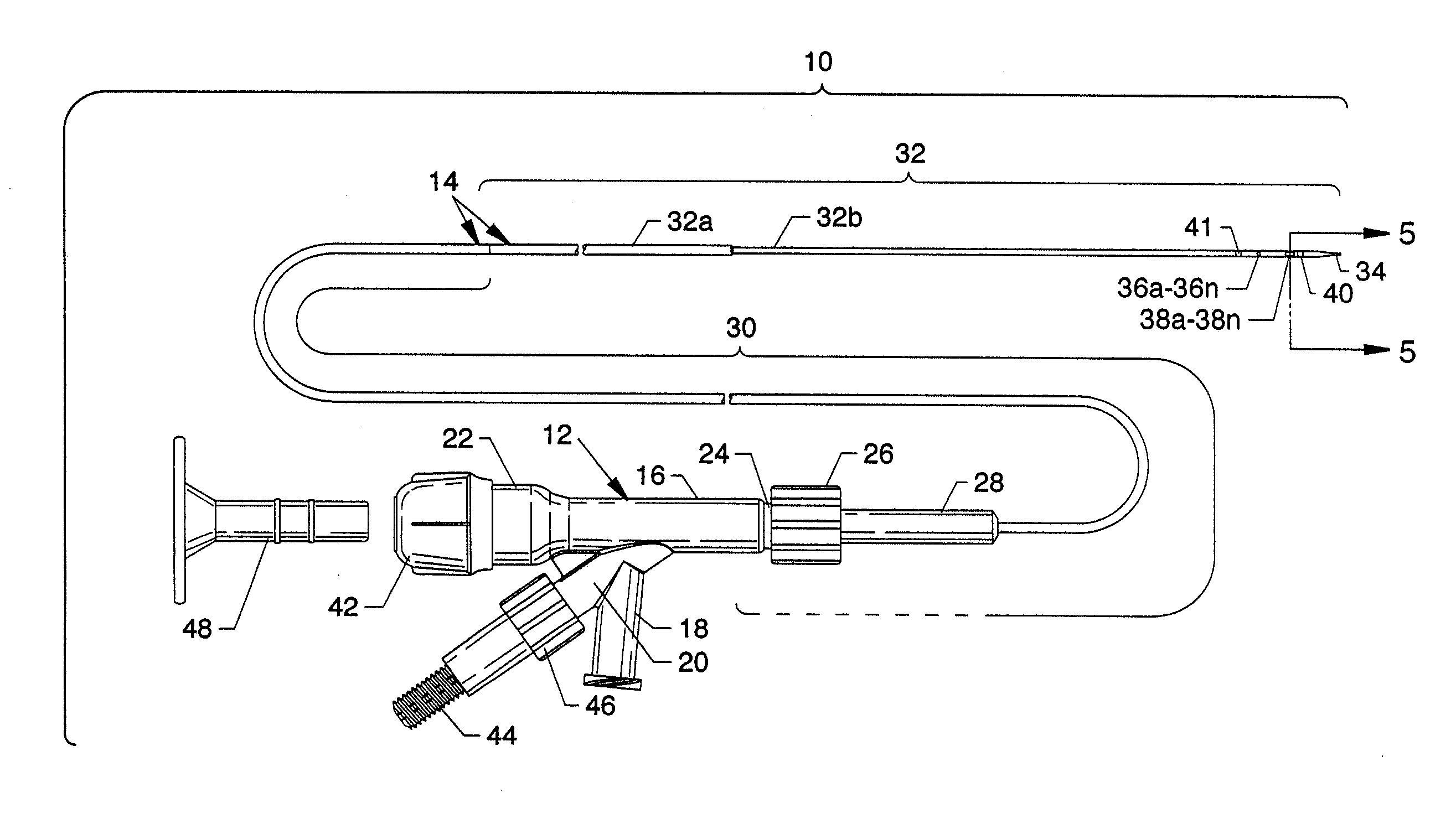
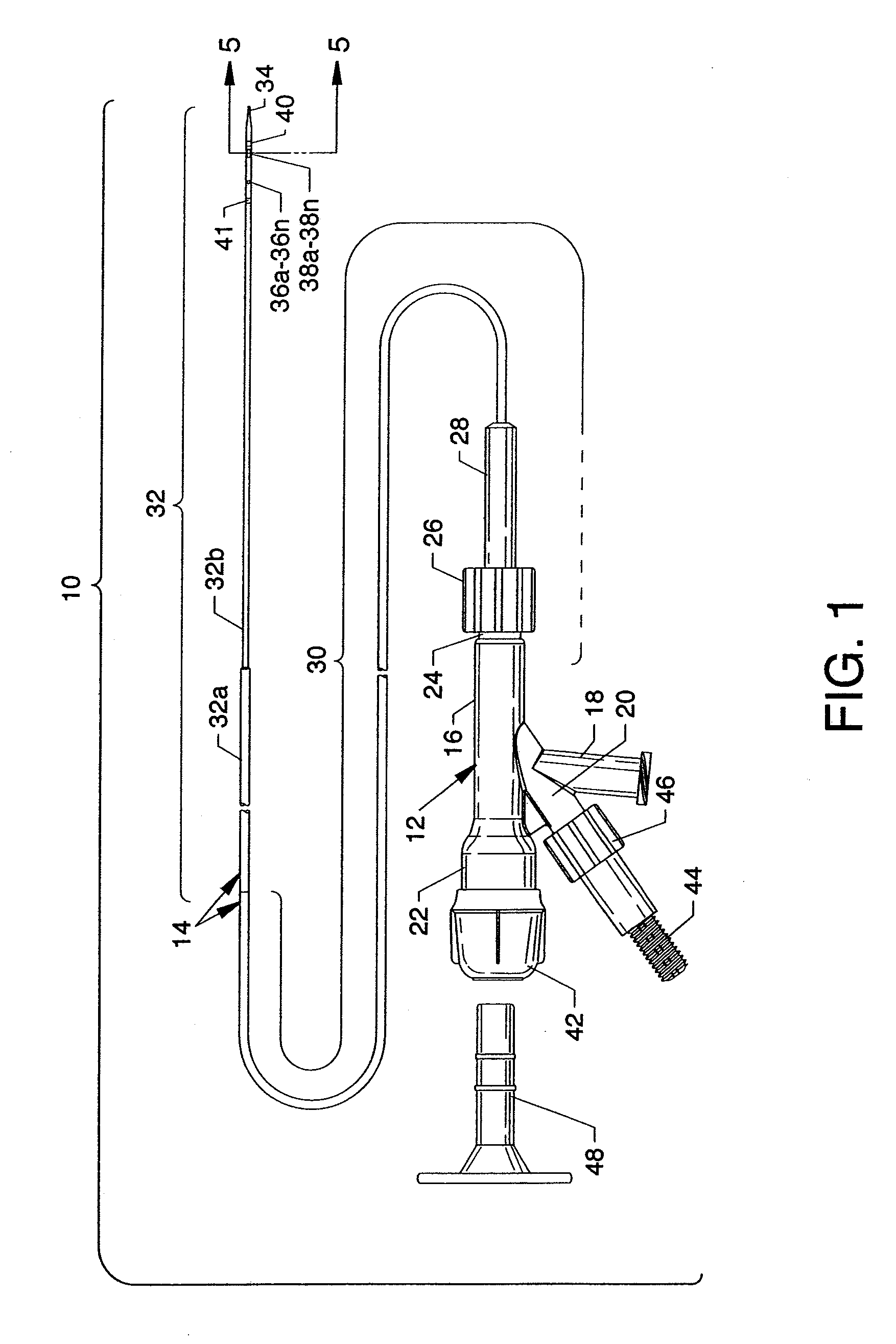
[0064]FIG. 1 is a plan view of the visible components of a miniature flexible thrombectomy catheter 10, the present invention, including a one-piece manifold 12 having multiple structures extending therefrom or attached thereto and including a configured catheter tube 14 and other components as described herein. Preferably, the catheter tube 14 includes a hydrophilic coating to enhance deliverability along the vasculature or other structure. The visible portion of the one-piece manifold 12 includes a central tubular body 16, a threaded exhaust branch 18, and a high pressure connection branch 20 extending angularly from the central tubular body 16, a cavity body 22 extending proximally from the central tubular body 16 and partially shown and extending distally from the central tubular body 16, and a threaded connection port 24. The proximal end of the catheter tube 14 secures to the manifold 12 by the use of a Luer fitting 26 accommodated by the threaded connection port 24. The proxi...


PUM

PropertyMeasurementUnit
diameteraaaaaaaaaa
strengthaaaaaaaaaa
pressureaaaaaaaaaa

Abstract

The present invention pertains to a miniature flexible thrombectomy catheter having one or more flexible miniature noncollapsing tubular portions including pushable and torqueable structure for introduction into the smaller vessels in neurovascular regions. A jet body having an arcuate fluid jet emanator is incorporated in order to minimize size at the distal portion of a minimally sized catheter tube.

Description

CROSS REFERENCE TO RELATED APPLICATION[0001]This application is a divisional of U.S. application Ser. No. 11 / 702,995, filed on Feb. 26, 2007. This application is related to U.S. application Ser. No. 10 / 455,096, filed on Jun. 5, 2003, and to U.S. application Ser. No. 11 / 096,592, filed on Apr. 1, 2005; both of which are continuations-in-part of U.S. application Ser. No. 10 / 198,264 filed on Jul. 16, 2002, now U.S. Pat. No. 6,875,193; which is a continuation-in-part of U.S. application Ser. No. 09 / 888,455, filed on Jun. 25, 2001, now U.S. Pat. No. 6,755,803; which is a continuation-in-part of U.S. application Ser. No. 09 / 356,783, filed on Jul. 17, 1999, now abandoned; which is a division of U.S. application Ser. No. 09 / 019,728, filed on Feb. 6, 1998, now U.S. Pat. No. 5,989,210.BACKGROUND OF THE INVENTION[0002]The present invention is for a thrombectomy catheter device, in general, and more particularly, to a thrombectomy catheter device incorporating a miniature distal portion for intr...

Claims


Application Information

Patent Timeline
Patent Type & Authority Applications(United States)
IPC IPC(8): B23P17/04
CPCA61B17/32037A61B2017/00526A61B2017/22038A61M25/0054A61M25/007Y10T29/49913Y10T29/49885Y10T29/494Y10T29/49927Y10T29/49778Y10T29/49929A61M2025/0183
Inventor KOZAK, DEBRA M.BALL, DOUGLAS J.TEDESCHENDORF, JOHN L.THOR, ERIC J.MORRIS, DAVID B.BONNETTE, MICHAEL J.WEISEL, STEPHEN E.
Owner BOSTON SCI MEDICAL DEVICE LTD
Why Eureka
Try Eureka