Razors

a technology of razors and lubricating fluid, which is applied in the direction of white arms/cold weapons, thrust weapons, weapons, etc., can solve the problems of difficult control of the delivery of fluid products for application to the skin, and proposals suffer the same drawbacks, and achieve the acceptable dispensing rate of fluid during shaving. , the charging rate of capacitors c6 is slow

Active Publication Date: 2008-11-27
THE GILLETTE CO
View PDF17 Cites 31 Cited by
  • Summary
  • Abstract
  • Description
  • Claims
  • Application Information

AI Technical Summary

Benefits of technology

[0041]Terminal T3,3 is connected to the electrode in the razor cartridge. Accordingly, when that electrode is brought into contact with or close proximity to the body of a user who is holding the handle connected to terminal T2,1, an additional path to ground is made, via a capacitor C7 and whatever resistance and capacitance the user's body has. This has the effect of slowing the charging rate of capacitor C6 such that, when the clock input of IC1:B goes high, the ‘D’ input is still low and so Q goes low. As described in more detail below the pulse generator and pump drive circuit 63 shown in FIG. 9 is responsive to a falling edge, and thus the transition of signal Q to low provides a suitable trigger signal.
[0042]Referring to FIG. 9, IC1:C is a timer circuit (in this embodiment a standard 555 timer IC) which provides the basis of a pulse generator and the trigger input TRG of which is capacitively coupled by capacitor C12 with a terminal T3,2 that is connected to the output terminal T3,1 of the comparator 62. Each side of the capacitor C12 is connected to the +5V rail 71 through a respective resistor R8, R9 so that when the Q output of the comparator 62 goes low as described above, a trigger signal is delivered to the trigger input TRG of IC1:C which immediately responds by causing a predetermined voltage pulse to be emitted at the output OUT of IC1:C. The timing circuit (R10, C14) determines the duration, i.e. the pulse width, of the output pulse in accordance with a voltage level supplied to a threshold input THR of IC1:C. The threshold voltage level, and hence the duration of the output pulse, is adjustable and is set by the adjustment of a potentiometer R10 that is wired as a variable resistor connected on one side to the +V rail and on the other side to ground via a capacitor C14. Thus, the output pulse is interrupted after the pulse duration. Although not provided for in the circuit as illustrated, there could then be a delay before the pulse generator can be triggered to emit a further output pulse. A circuit incorporating a microprocessor control could provide this as well as other additional control parameters. The output pulse of the pulse generator is supplied to the control input of a switching device, shown to be a field effect transistor (FET) Q2, which switches on and off the supply of battery power to the motor of pump 24. A diode D4 is connected in parallel with FET Q2 to protect against any back EMF generated by the pump motor. It will be understood that the pump 24 is actuated for the predetermined duration of the output pulse generated by the pulse generator, for metering a corresponding quantity of fluid to the dispensing outlet at the blade unit 2, when the blade unit is moved into contact with the skin of a user holding the razor by the handle 1. A suitable period of actuation of the pump is from 0.1 to 2 seconds, more particularly 0.2 to 1 second, and most preferably 0.3 to 0.6 seconds. An actuation period of 0.4 seconds is believed to produce an acceptable dispensing rate for lubricating fluid during shaving. The razor may be equipped with a control element to allow the razor user to adjust the actuation period between certain limits to suit personal preferences, by varying the setting of the variable register R10. When a delay is ensured between successive actuations it may be at least as long as the period for actuation and may be from 1 to 10 seconds, such as 2 to 6 or 8 seconds, a delay of around 4 seconds being considered appropriate for most shavers.

Problems solved by technology

With this system, and with other prior art arrangements, it is difficult to control the delivery of fluid product for application to the skin so as to ensure a satisfactory metering rate without excessive amounts of product being dispensed.
These proposals suffer the same drawbacks as those discussed above.

Method used


Image

  • Razors
  • Razors
  • Razors

Examples


Embodiment Construction

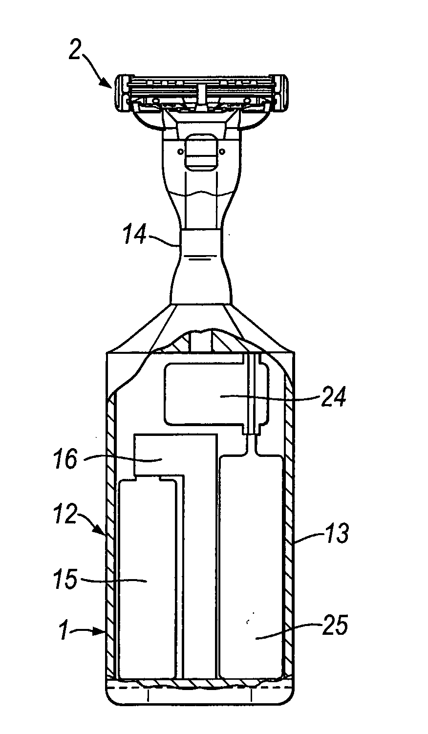
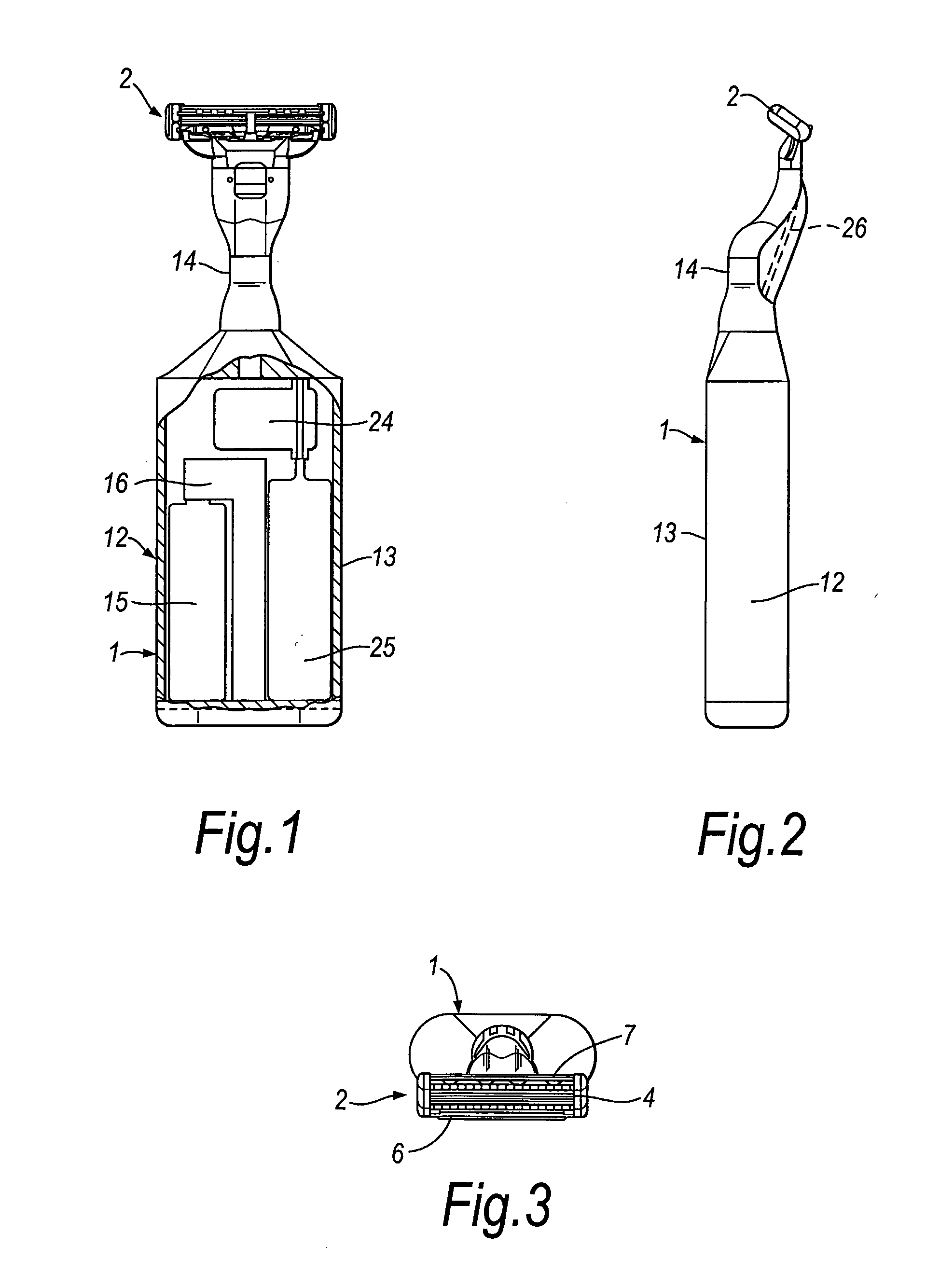
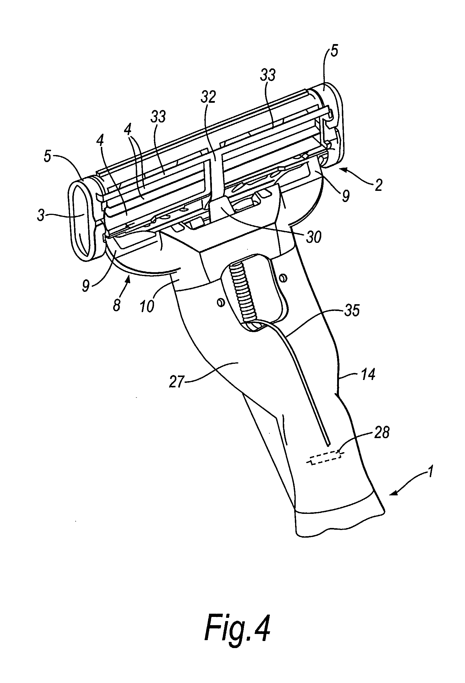
[0026]The safety razor illustrated in the drawings has a handle 1 and a blade unit or cartridge 2 detachably mounted on the upper end of the handle. The blade unit includes a generally rectangular frame 3, and a plurality of blades 4, e.g. 3, 4 or 5 blades, with substantially parallel sharp cutting edges, disposed in the frame and held in place by metal clips 5 positioned around the frame 3 at the opposite ends of the blade unit 2. A guard structure 6 including a strip of elastomeric material is provided on the frame for contacting the skin in front of the blades, and a cap structure 7 is provided on the frame for contacting the skin behind the blades during the performance of a shaving stroke. The frame is pivotally carried on yoke member 8 having a pair of arms 9 which extend from a hub 10 and are journalled in opposite ends of the frame 2 so that the blade unit 2 can pivot relative to the handle 1 about an axis substantially parallel to the blade edges. The hub 10 is connected de...


PUM


Abstract

A razor, especially a safety razor, comprises a fluid delivery system including a pump (24) for conducting a fluid, such as a lubricant, from a reservoir (25) for application to the skin, and a control device (16) for actuating the pump (24) when the razor is brought into contact with the skin by a person holding the razor, and deactuating the pump (24) after a certain time of actuation, e.g. 0.1 to 2 seconds. The control device is arranged to ensured a delay of 1 to 10 seconds between successive actuations, and so that the pump is actuated only every second third or fourth shaving stroke.

Description

FIELD OF THE INVENTION[0001]This invention relates to razors. It is especially applicable to a safety razor, i.e. a razor with one or more blades or foils with sharp cutting edges, although the invention in its broadest concept can also be applied to dry razors, that is razors in which a foil and an undercutter are moved relative to each other for severing hairs with a shearing action. The invention is particularly described herein embodied in a safety razor.BACKGROUND OF THE INVENTION[0002]There have been many proposals to provide a safety razor with a dispensing system for delivering to the skin during shaving a shaving enhancement product, such as a shaving foam or other lubricating fluid, the product being stored within a reservoir ready for use. According to some of these prior proposals the reservoir is accommodated within the razor handle, although other arrangements have been suggested, such as clipping the razor structure to a pressurised container, as described in our earl...

Claims


Application Information

Patent Timeline
Patent Type & Authority Applications(United States)
IPC IPC(8): B26B21/00B26B19/40B26B21/44
CPCB26B19/40B26B21/4056B26B21/44B26B21/446B26B21/443
Inventor CLARKE, SEAN PETER
Owner THE GILLETTE CO
Why Eureka
Try Eureka