Ethernet interconnection apparatus and method

a technology of interconnection and equipment, applied in the direction of power distribution line transmission, repeater circuit, line-transmission details, etc., can solve the problems of inefficiency, cost, complicated, etc., and achieve the effect of avoiding inefficiency, saving resources, and improving efficiency

Inactive Publication Date: 2008-11-27
SIXNET
View PDF6 Cites 37 Cited by
  • Summary
  • Abstract
  • Description
  • Claims
  • Application Information

AI Technical Summary

Problems solved by technology

Applying power to various circuits typically requires the use o

Method used


Image

  • Ethernet interconnection apparatus and method
  • Ethernet interconnection apparatus and method
  • Ethernet interconnection apparatus and method

Examples


Embodiment Construction

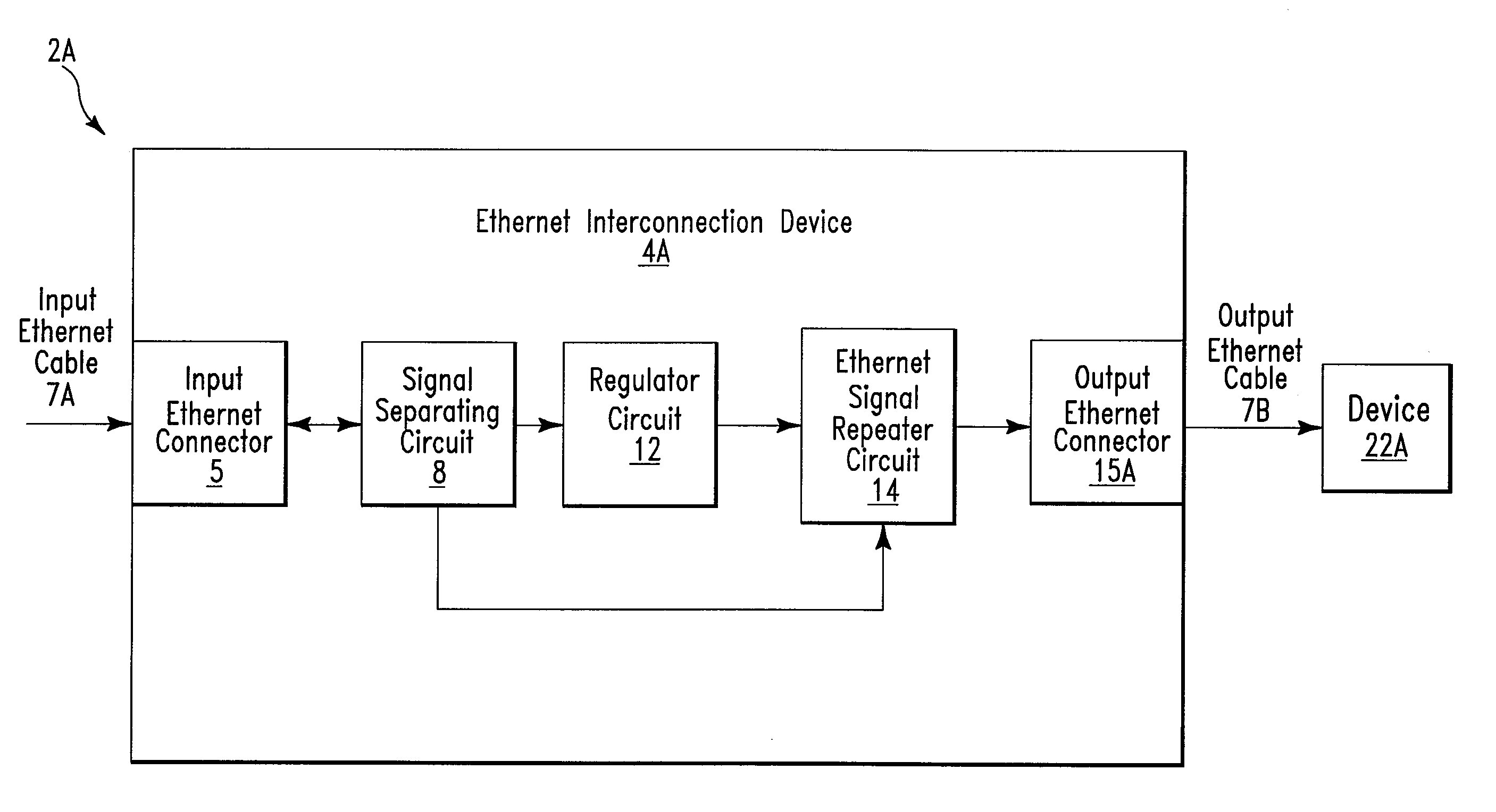
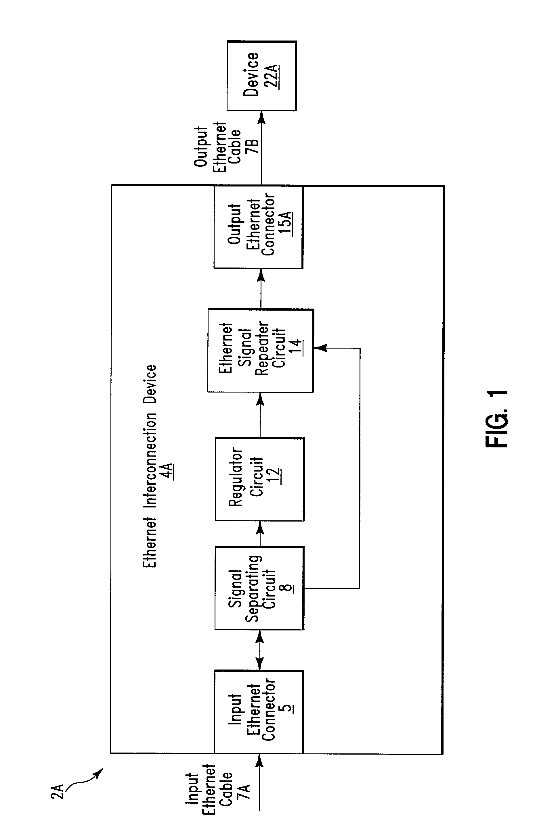
[0045]FIG. 1 illustrates a block diagram of a system 2A comprising an Ethernet interconnection device 4A, in accordance with embodiments of the present invention. Ethernet interconnection device 4A may comprise any type of Ethernet interconnection device including, inter alia, an Ethernet repeater, a router, a hub, an Ethernet switch, etc. System 2A comprises Ethernet interconnection device 4A, an input Ethernet cable 7A, an output Ethernet cable 7B, and an industrial / commercial device 22A. Ethernet cable 7A and 7B may comprise any type of Ethernet cable including, inter alia, Category 5 (or higher) cable. Ethernet cable 7A and 7B may comprise conductors of any gauge including, inter alia, 24 gauge, 22 gauge, etc. Ethernet cable 7A is used to retrieve data signals (e.g., I / O signals) and power signals (e.g., power over Ethernet (POE)) from an external apparatus (e.g., a computer). Ethernet cable 7B is used to transmit data signals (e.g., I / O signals) to industrial / commercial device ...


PUM


Abstract

An Ethernet interconnection device and method. The apparatus includes an input Ethernet connector, a signal separating circuit electrically connected to the input Ethernet connector, a voltage regulator circuit electrically connected to the signal separating circuit, an Ethernet signal repeater circuit electrically connected to the signal separating circuit, and an output Ethernet connector electrically connected to the Ethernet signal repeater circuit. The receiving circuit receives a first voltage signal and an Ethernet data signal from an Ethernet cable. The signal separating circuit separates the first voltage signal from the Ethernet data signal. The voltage regulator conditioning circuit generates a second voltage signal from the first voltage signal. The second voltage signal is a power source the Ethernet signal repeater circuit. The output Ethernet connector is configured to electrically conduct an regenerated Ethernet data signal from the Ethernet signal repeater circuit to an industrial/commercial device.

Description

FIELD OF THE INVENTION[0001]The present invention relates to an apparatus and associated method for generating a voltage source from power retrieved from an Ethernet cable and using the voltage source to apply power to circuitry internal to an Ethernet interconnection device.BACKGROUND OF THE INVENTION[0002]Applying power to various circuits typically requires the use of an apparatus that may be inefficient, costly, and complicated. Accordingly, there exists a need in the art to overcome the deficiencies and limitations described herein above.SUMMARY OF THE INVENTION[0003]The present invention provides an Ethernet interconnection device comprising:[0004]an input Ethernet connector configured to interface said Ethernet switch device to an Ethernet cable, wherein said input Ethernet connector is further configured to receive a first power over Ethernet (POE) signal from said Ethernet cable, and wherein said first POE signal comprises a first voltage signal and a first Ethernet data si...

Claims


Application Information

Patent Timeline
IPC IPC(8): H04B3/54
CPCH04B3/36H04B3/44H04L12/10H04L12/46
Inventor SCHOENBERG, STEVE ALANO'CONNOR, MICHAEL JERRYFRIEDMAN, JACK P.
Owner SIXNET
Why Eureka
Try Eureka