Color display apparatus

a display apparatus and color technology, applied in static indicating devices, instruments, non-linear optics, etc., can solve the problems of inability to provide the known method, the inability to display with intermediate brightness, and the inability to provide continuous hue, etc., to achieve simple display panel structure, high resolution, and high definition

Inactive Publication Date: 2008-11-27
CANON KK
View PDF5 Cites 6 Cited by
  • Summary
  • Abstract
  • Description
  • Claims
  • Application Information

AI Technical Summary

Benefits of technology

[0020]The present invention is directed to a display apparatus and an image forming apparatus which are capable of expressing neutral colors with high resolution and high definition using a simple display panel structure, and which are also capable of accurately presenting an image based on an input image signal.

Problems solved by technology

However, red and blue are displayed using birefringence and cannot be displayed with intermediate brightness.
However, continuous hue, which is necessary for displaying natural images, cannot be provided by the known method.
As a result, the light utilization efficiency is reduced.
Although this structure is advantageous in that analog gradation can be displayed, there is also a problem that the number of color filter processes is increased.
Therefore, there is a problem that the resolution is reduced when natural images are displayed.

Method used


Image

  • Color display apparatus
  • Color display apparatus
  • Color display apparatus

Examples


first embodiment

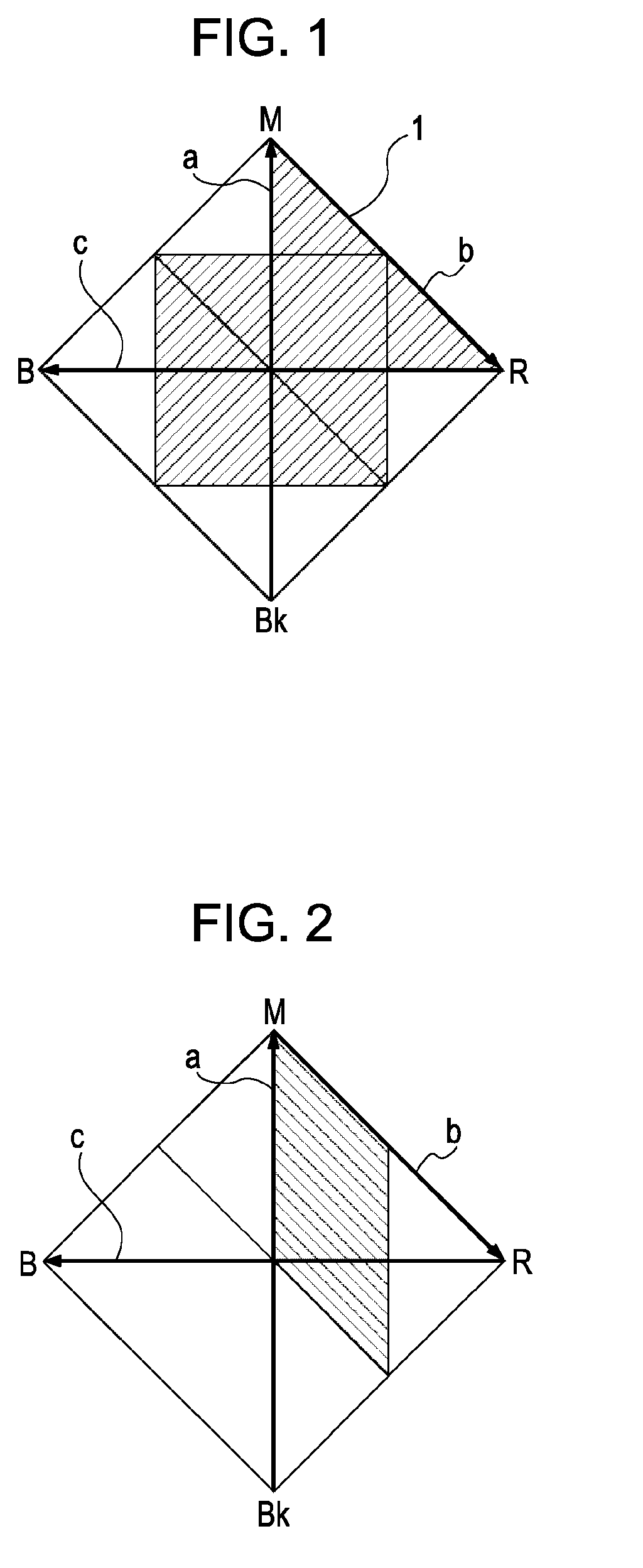
[0063]An embodiment of the present invention in which first color elements in two pixels are combined will be described. The first color elements include magenta color filters. The manner in which the color can be continuously varied on the RB plane will be described.

[0064]Two magenta sub-pixels 1 in two pixels are used as a pair. The birefringence is continuously controlled in each of the magenta sub-pixels 1 over the sections A, B, and C. It is assumed that a single color is expressed by combining the magenta sub-pixels. Two vectors extending from the origin Bk to two points on the sections A, B, and C can be defined by setting the two points. When the points are moved along the respective sections, an area is defined on the RB plane by adding the two independent vectors. This area shows the range of color that can be displayed by combining the magenta sub-pixels in the two pixels.

[0065]As described in detail below, the above-mentioned area is shown as the shaded area in FIG. 1. S...

second embodiment

[0087]FIG. 5 show areas that cannot be displayed by the method according to the first embodiment in which the color on the RB plane is displayed by combining the first color elements in two pixels. The non-displayable areas can be reduced by combining the first color elements in three pixels. This will be described below.

[0088]Areas 1 shown in FIG. 5 can be expressed by displaying blue at the magenta sub-pixel 1 in a third pixel and combining the third pixel with the above-described two pixels. In this case, the displayable area is obtained by shifting the area shown in FIG. 1 by a distance corresponding to the coordinates of the blue display in the third pixel. As a result, the shaded area shown in FIG. 6 is obtained as the displayable area.

[0089]However, referring to FIG. 5, areas 2 and 3, which are low-gradation-level areas of colors close to primary colors red and blue, still cannot be displayed. These non-displayable areas can be reduced, as described below in the examples, due...

examples

[0091]Examples of the present invention will be described in detail below.


PUM

PropertyMeasurementUnit
voltageaaaaaaaaaa
brightnessaaaaaaaaaa
colorsaaaaaaaaaa

Abstract

A color display apparatus includes a plurality of color elements, each color element including an electro-optical element in which retardation varies in accordance with a voltage applied to the electro-optical element and a color filter provided on the electro-optical element. The color elements include two or more first color elements in which the color filters transmit light of two of three primary colors, each first color element receiving a voltage that continuously varies the retardation of the electro-optical element in a range in which brightness of the first color element varies and a range which starts from the retardation corresponding to the maximum brightness and in which hue of the first color element varies between the two of the three primary colors. The two or more first color elements function as a unit of color display for the two of the three primary colors.

Description

BACKGROUND OF THE INVENTION[0001]1. Field of the Invention[0002]The present invention relates to a display apparatus capable of displaying multicolor images.[0003]2. Description of the Related Art[0004]Recently, the technology of electronic displays, such as liquid crystal displays, plasma displays, and organic electroluminescence displays has been rapidly developed and has come into widespread use. The electronic displays generally use a color display method in which each pixel includes three sub-pixels corresponding to three primary colors: red (R), green (G), and blue (B). The sub-pixels are arranged in parallel, and various colors are presented by spatial color mixture. Each of the sub-pixels is capable of expressing the corresponding color in various tones, and is controlled so as to provide substantially continuous gradation. Thus, a full color display can be obtained.[0005]Many electronic displays include sub-pixels having color filters corresponding to the three RGB colors, ...

Claims


Application Information

Patent Timeline
Patent Type & Authority Applications(United States)
IPC IPC(8): G02F1/1335
CPCG02F1/133514G02F1/1393G09G3/3607G09G2300/0452G09G2300/0491
Inventor ASAO, YASUFUMI
Owner CANON KK
Why Eureka
Try Eureka