
Labeler for dispensing labels adhering to a backing strip

a labeler and backing strip technology, applied in the field of labeling apparatus, can solve the problems of affecting the operation of this particular apparatus, affecting the ability to apply more than one label at one time to a range of articles, and affecting the quality of the product, so as to achieve the effect of easy labeling, greater speed of operation and easy operation

Inactive Publication Date: 2004-01-22
JET STICK
View PDF9 Cites 5 Cited by
  • Summary
  • Abstract
  • Description
  • Claims
  • Application Information

AI Technical Summary

Benefits of technology

[0067] A stepper motor is utilised at this point in the apparatus in order to compensate for the inherent high detent force and therefore prevent overrun of the label. Any suitable compensation means may be employed although a stepper motor is preferred. Operation of the drive wheel in conjunction with the stepper motor accurately presents the label to the delivery point
[0071] This will allow the position of the object to be determined without the object or the object detector crowding the area around the delivery point at which the label is delivered to an object.
[0088] It should also be appreciated that there are a number of alternative uses for the invention as almost any label applicator could benefit from the principles of this invention. The air application enables irregular objects to be more easily labelled.

Problems solved by technology

Any problems in generating the vacuum can affect the operation of this particular apparatus.
Further, where the article to which the label is being attached is a fruit that may be easily bruised, the contact between the surface of the fruit and the label fixed to the bellows may result in unwanted damage to the fruit.
Whether the vacuum is created at a single vacuum station or whether the apparatus is a high speed labelling machine with a vacuum drum transferring labels cut from a continuous roll held onto the drum via a vacuum port and then requiring separate edges to force the label against a container, there are similar problems associated with these inventions.
In addition, the ability to apply more than one label at one time to a range of articles is limited.

Method used


Image

  • Labeler for dispensing labels adhering to a backing strip
  • Labeler for dispensing labels adhering to a backing strip
  • Labeler for dispensing labels adhering to a backing strip

Examples


Embodiment Construction

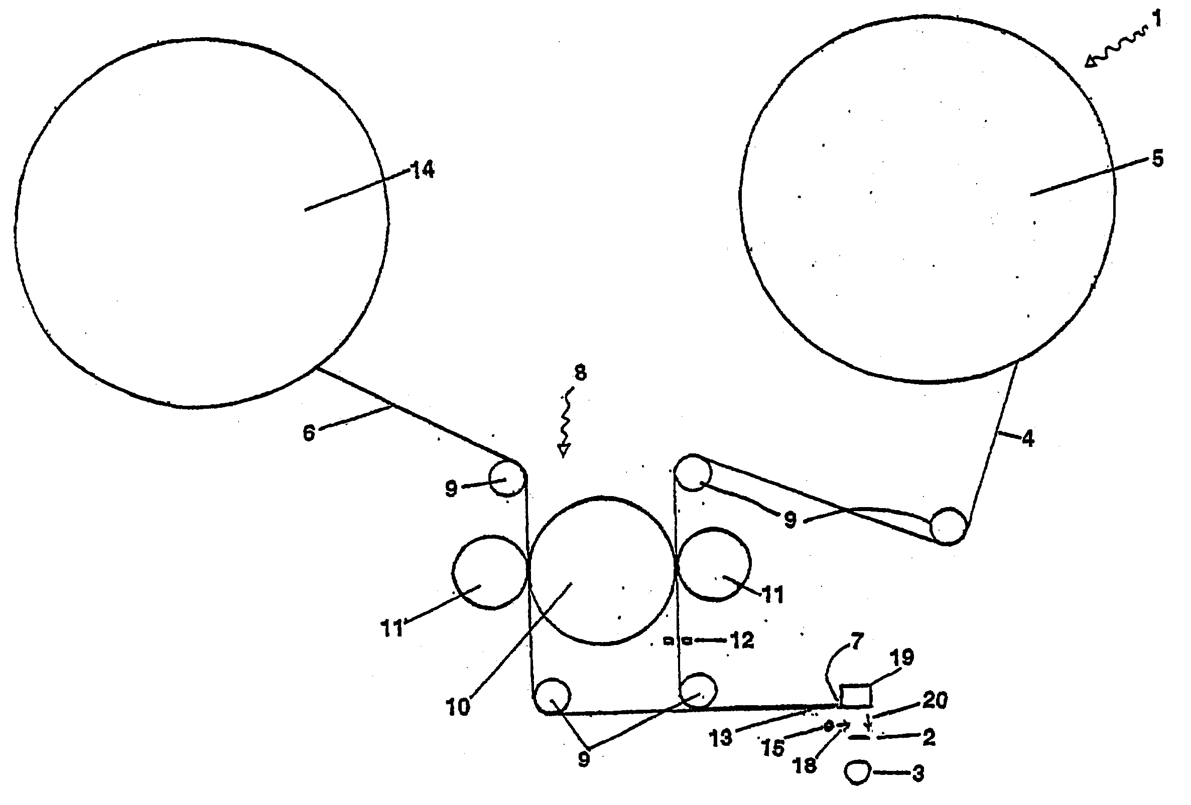
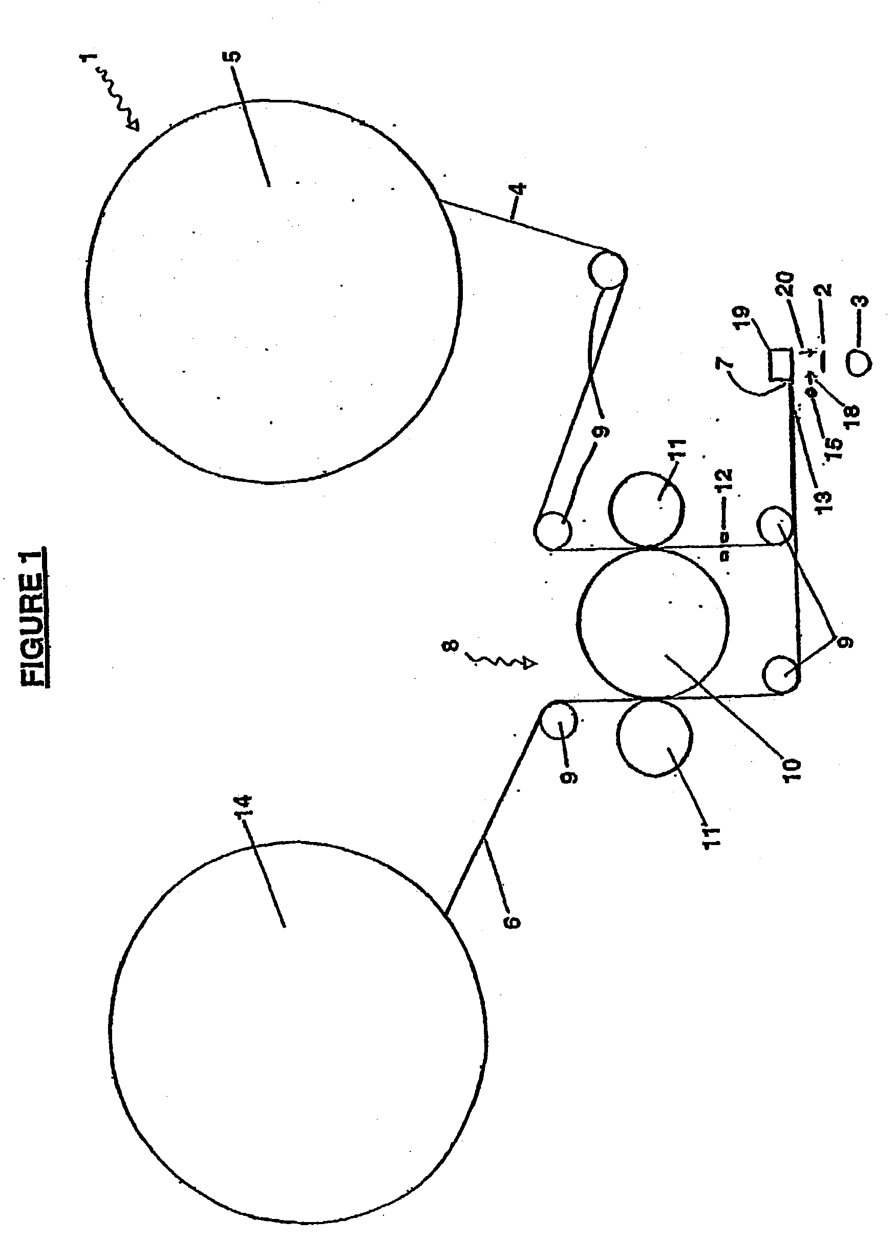
[0096] With reference to the diagrams by way of example only there is provided apparatus (generally indicated by arrow 1) for applying a label (2) to an object (3).

[0097] The process of delivering a label (2) to the object (3) is triggered by one of two things. A photo-electric sensor (not shown) detects an object (3) or a signal from a host sizer computer (not shown). The labelling apparatus (1) is timed to the sizing computer / machine by the same or additional sensing apparatus linked to or separate from the photo-electric sensor that detects the object.

[0098] The object detector is positioned at the front of the labelling apparatus (1) and is synchronised by a shift register in the electronic control board of the object detector, to allow the position of the object (3) to be determined, without the object (3), or the object detector crowding the area around the delivery point (7) at which the label (2) is delivered to an object (3).

[0099] The apparatus (1) includes a label source ...


PUM

PropertyMeasurementUnit
Forceaaaaaaaaaa
Flow rateaaaaaaaaaa
Sizeaaaaaaaaaa

Abstract

The present invention relates to a labelling apparatus (1) for applying a label (2) to an object (3), including a sensing apparatus capable of identifying the position of an object relative to the labelling apparatus, and an applicator (19) to facilitate the application of the label onto an object at the preferred time, and a means (18) for advancing at least one label strip to which at least one label is removably adhered, and a detaching station (13) which is capable of partially detaching the adhesive label from the backing tape of the label strip, and the labeling apparatus characterised in that it includes a first pressurised air flow (18) capable of blowing air at the label to prevent the label from reattaching itself to the backing tape of the label strip, and a second sensing apparatus, capable of detecting the end of the label, and trigger means to activate a secondary air flow (19) for a time period to enable an blown from the secondary air flow to direct the label onto the object.

Description

[0001] This invention is directed to improvements in and relating to the application of adhesive labels on to objects. In particular, it is envisaged the methods and apparatus of this invention will have particular use in relation to the application of labels on to fruit either singularly, or via multiple application to all fruit positioned in a fruit tray.[0002] However, this invention may have applications outside this field.[0003] There are a number of machines, apparata or processes for labelling, or dispensing labels on to objects. Some of these applications include air blast devices for applying labels, whilst others require contact between the labelling apparatus and the object to which the label is applied.[0004] For example, New Zealand Patent No. 206735 relates to a labelling machine including a rotating labelling head. A strip of adhesive labels is carried on a reel. This strip is passed along a plate at the end of which the label is stripped from the backing and held by ...

Claims


Application Information

Patent Timeline
IPC IPC(8): B65C9/00B65C9/18B65C9/40B65C9/42
CPCB65C9/0006B65C9/1884B65C9/42Y10T156/171Y10T156/1768Y10T156/1707B65C2009/401
Inventor NORRIS, HOWARD
Owner JET STICK
Learn More