Locator

a technology of locators and actuators, applied in the field of locators, can solve the problems of prone to false measurement, complex measurement process, ambiguity, etc., and achieve the effects of simple visual output devices, high detail, and low complexity

Inactive Publication Date: 2013-08-01
ROBERT BOSCH GMBH
View PDF12 Cites 5 Cited by
  • Summary
  • Abstract
  • Description
  • Claims
  • Application Information

AI Technical Summary

Benefits of technology

[0012]The locator may have a multiplicity of first electromagnetic devices which are arranged next to one another and which are successively operated on the push-pull measurement bridge. This allows the article to be sensed in one or two dimensions, which means that the article can be localized more precisely or a boundary of the article, for example an edge, can be found more easily.
[0013]In one preferred embodiment, the measurement results attained using the various first electromagnetic devices are visually displayed by defining display regions on a visual output device which are each associated with one of the first electromagnetic devices. In this case, the arrangement of the display regions preferably corresponds to the arrangement of the first electromagnetic devices. A user can thus be presented with a visual representation of the measurement result which can be grasped intuitively and has a high level of detail.
[0014]A distance of the article from the locator can correspond to a change of color in the visual output device. If the visual output device is kept simple, and hence inexpensive, for example in the form of a few light-emitting diodes, then a change of color allows the measurement result to be presented more precisely with little complexity, it being possible to use multicolored LEDs. If the visual output device is more complex, for example in the form of a graphical panel output with color capability, such as a liquid-crystal display with graphics capability, then the distance of the article can be presented graphically by a false color presentation. In this case too, the color presentation of the measurement results can lead to improved ease of use for a user.

Problems solved by technology

A fundamental problem for locators is that they tend to produce false measurements when a sensing sensitivity is increased.
The calibration can render the measurement process complex and ambiguous.

Method used


Image

  • Locator
  • Locator
  • Locator

Examples


Embodiment Construction

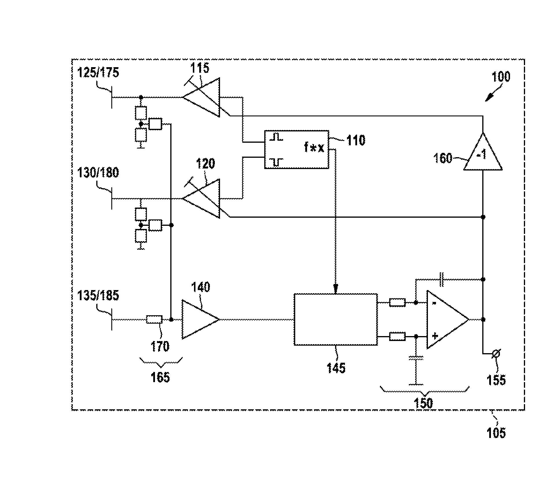
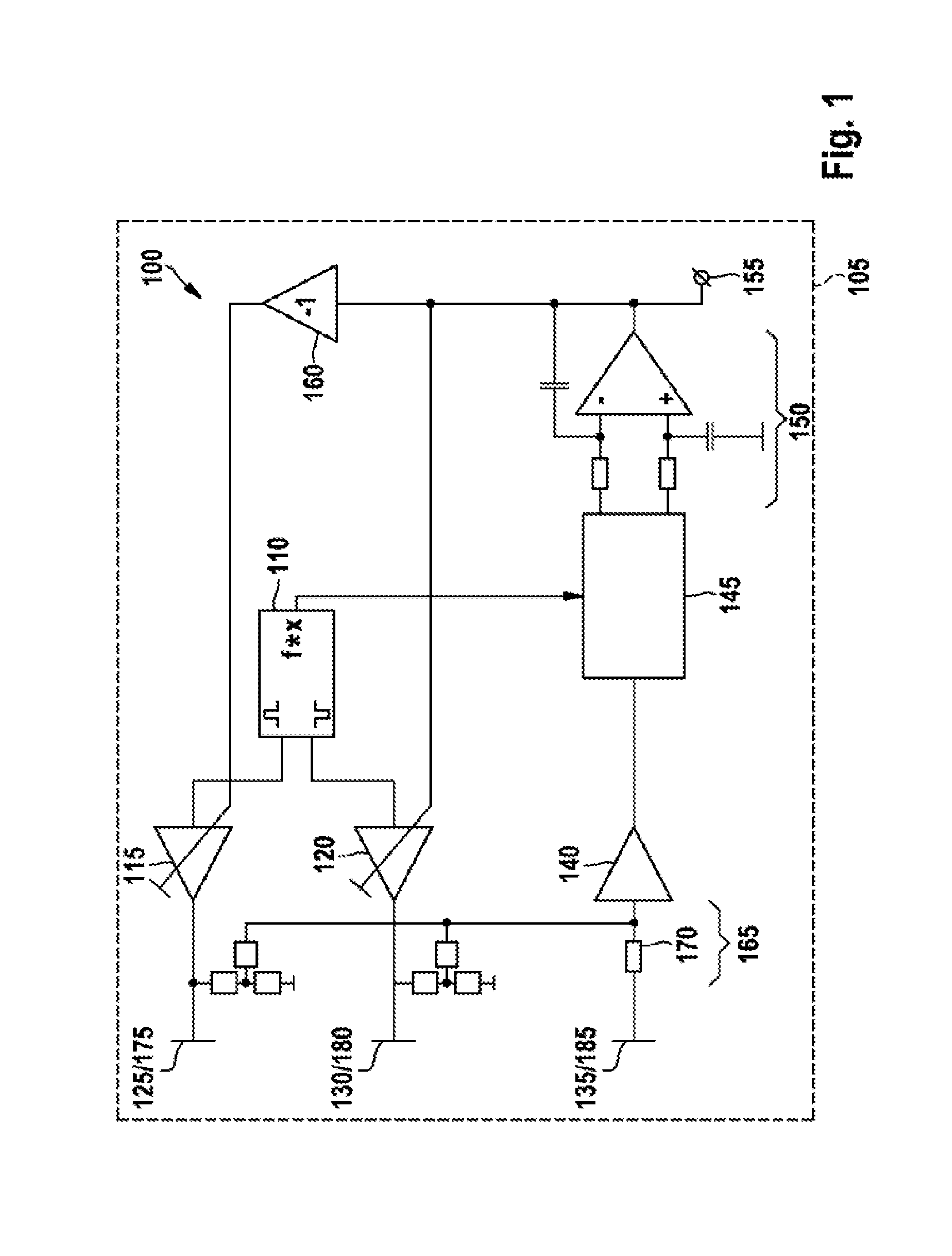
[0025]FIG. 1 shows a block diagram of a push-pull measurement bridge 100. The push-pull measurement bridge 100 is part of a locator 105 for sensing articles. Depending on the embodiment, the push-pull measurement bridge 100 can be used for sensing a dielectric article, for example made of wood, or for sensing a metallic article, for example made of steel. The text below first of all describes the embodiment which can be used to sense a dielectric article.

[0026]A clock generator 110 has two outputs at which it provides periodic alternating signals having a phase shift, preferably a 180° phase shift. The alternating signals may comprise square-wave, triangular-waveform or sinusoidal signals, in particular. The outputs of the clock generator are connected to a first controllable amplifier 115 and a second controllable amplifier 120, respectively. Each of the controllable amplifiers 115, 120 has a control input which it uses to receive a signal which controls a gain factor of the contro...


PUM


Abstract

A locator for detecting an article includes a push-pull measurement bridge configured to actuate a first and a second electromagnetic device in a variable ratio. Depending on the actuation the first electromagnetic device generates an alternating electromagnetic field in the region of the article. The locator further includes a comparator for detecting the article, should the variable ratio differ by more than a predetermined amount from a predetermined ratio.

Description

[0001]The invention relates to a locator. In particular, the invention relates to a locator having the features of claim 1 for sensing an article.PRIOR ART[0002]Various locators are known for sensing an article concealed in a wall. The article concealed in the wall may be a water, power or gas line, for example, which must not be damaged when working on the wall. On the other hand, the article may also be a wooden beam or another supporting structure, and the work needs to be carried out in the region of the supporting structure.[0003]In order to trace a metallic article, such as a steel water pipe, within the wall, a magnetic field is usually produced and a check is performed to determine whether the article influences the magnetic field. If the influence exceeds a predetermined amount, the article is sensed. A nonmetallic article, such as a wooden beam, can be detected by using its dielectric properties. To this end, an electrical field is produced and a check is performed to dete...

Claims


Application Information

Patent Timeline
Patent Type & Authority Applications(United States)
IPC IPC(8): G01R33/00
CPCG01V3/08G01V3/15G01R33/0011H03K17/955H03K17/9525
Inventor KRAPF, REINERZIBOLD, TOBIASALBRECHT, ANDREJ
Owner ROBERT BOSCH GMBH
Why Eureka
Try Eureka