Image Processing System

a technology of image processing and image, applied in the field of image processing system, can solve the problems of reducing user convenience, difficult to judge, and achieve the effect of preventing a confidentiality leakage and wasting storage spa

Active Publication Date: 2008-11-27
KONICA MINOLTA BUSINESS TECH INC
View PDF4 Cites 17 Cited by
  • Summary
  • Abstract
  • Description
  • Claims
  • Application Information

AI Technical Summary

Benefits of technology

[0019]The above-stated construction can prevent a confidentiality leak and a waste of the storage area in the image processing device because of a case in which the print request that has been executed in any of the image processing devices remains in the other image processing devices.
[0020]In the image processing system of the present invention, the image processing is any of print, transfer, Box storage, and server upload. In any case, the effect of the present invention can be obtained.

Problems solved by technology

In this case, if a user tries to print a document in an unfamiliar office environment such as a business trip destination, the user's convenience is reduced because it is difficult to judge to which of a plurality of multifunction peripherals should the user transmit document data of the document.
If the user cannot recognize which multifunction peripheral executed printing, a printed matter may be lost, or if a third party finds the printed matter, information of the printed matter may be leaked.
However, if document data is transmitted to each of a plurality of multifunction peripherals, it could cause a leak of information especially when a user prints a document in an unfamiliar office environment.
Also, when a user instructs any of a plurality of multifunction peripherals to execute printing, if the printing fails because of a failure of the multifunction peripheral, the user has to request the printing in a personal computer again.
Therefore, this is unsuitable for the user's convenience.

Method used


Image

  • Image Processing System
  • Image Processing System
  • Image Processing System

Examples


first embodiment

[1] First Embodiment

[0035]The following describes a first embodiment of the present invention.

(1) Structure of Image Forming System

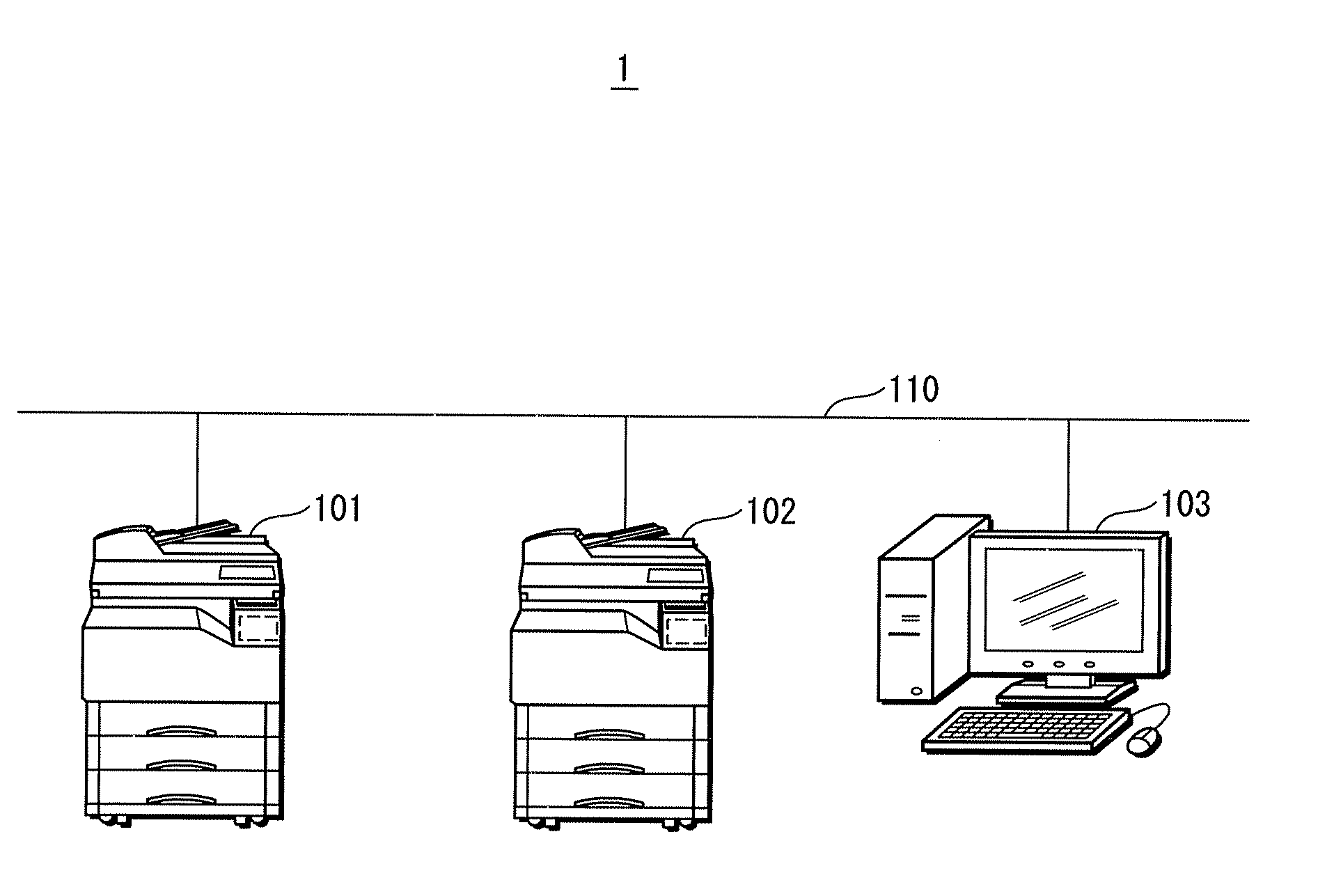
[0036]Firstly, a structure of an image forming system will be described. FIG. 1 shows a main structure of the image forming system. As shown in FIG. 1, in an image forming system 1, multifunction peripherals 101 and 102, and a personal computer 103 are connected to each other via, a LAN (local area network) 110. The multifunction peripherals 101 and 102, and the personal computer 103 perform IP (internet protocol) communication with each other via the LAN 110.

(2) Structures of Multifunction Peripherals 101 and 102

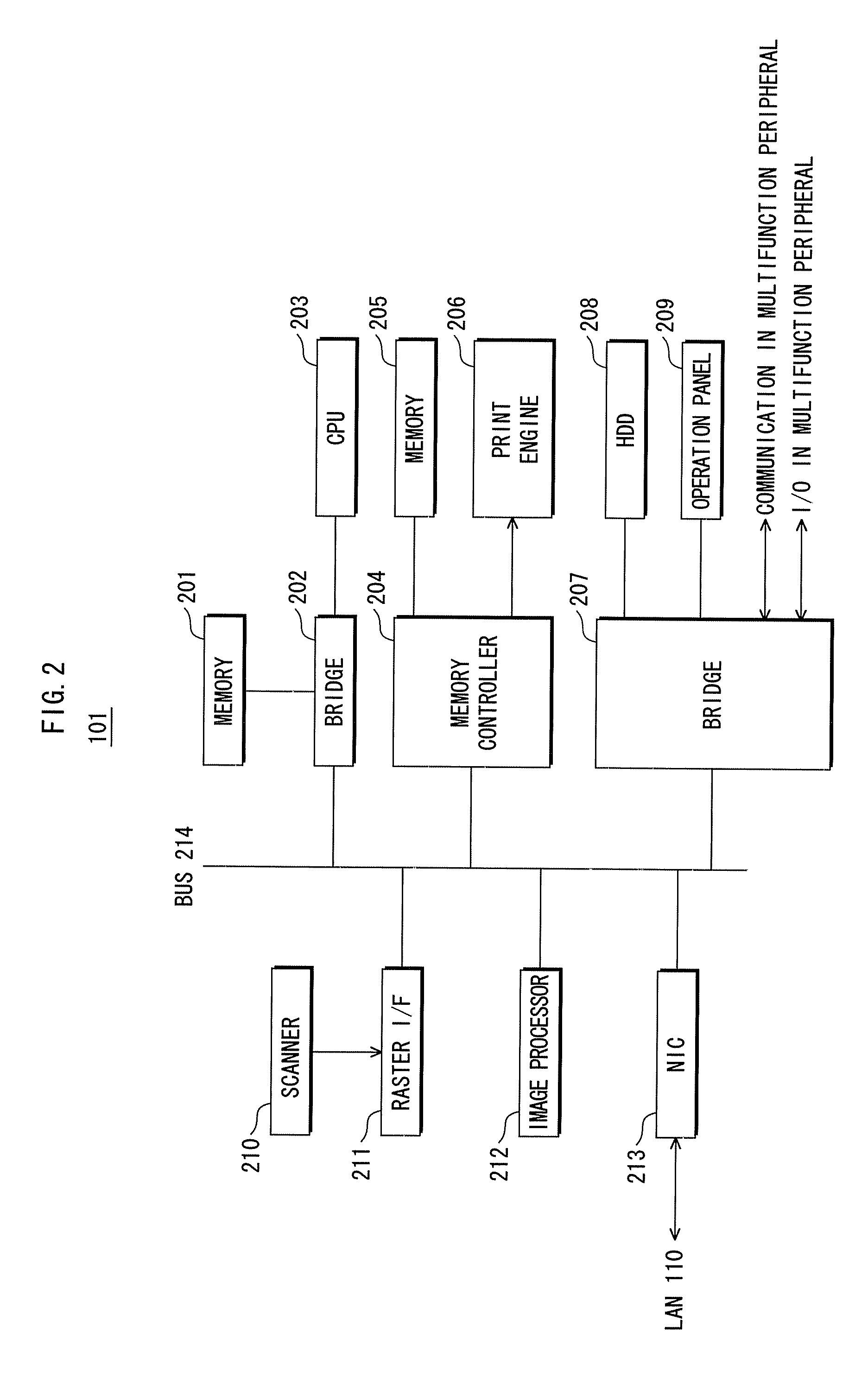
[0037]Next, a structure of the multifunction peripheral 101 will be described. Because the multifunction peripheral 102 has the same structure as the multifunction peripheral 101, the explanation of the multifunction peripheral 101 is applied to the multifunction peripheral 102.

[0038]FIG. 2 is a block diagram showing a main structure of the mult...

second embodiment

[2] Second Embodiment

[0069]The following describes a second embodiment of the present invention. An image forming system of the second embodiment has a similar construction to the image forming system of the first embodiment, but differs in a security measure associated with an image formation. This difference will be mainly described below.

(1) Communication Data Structure

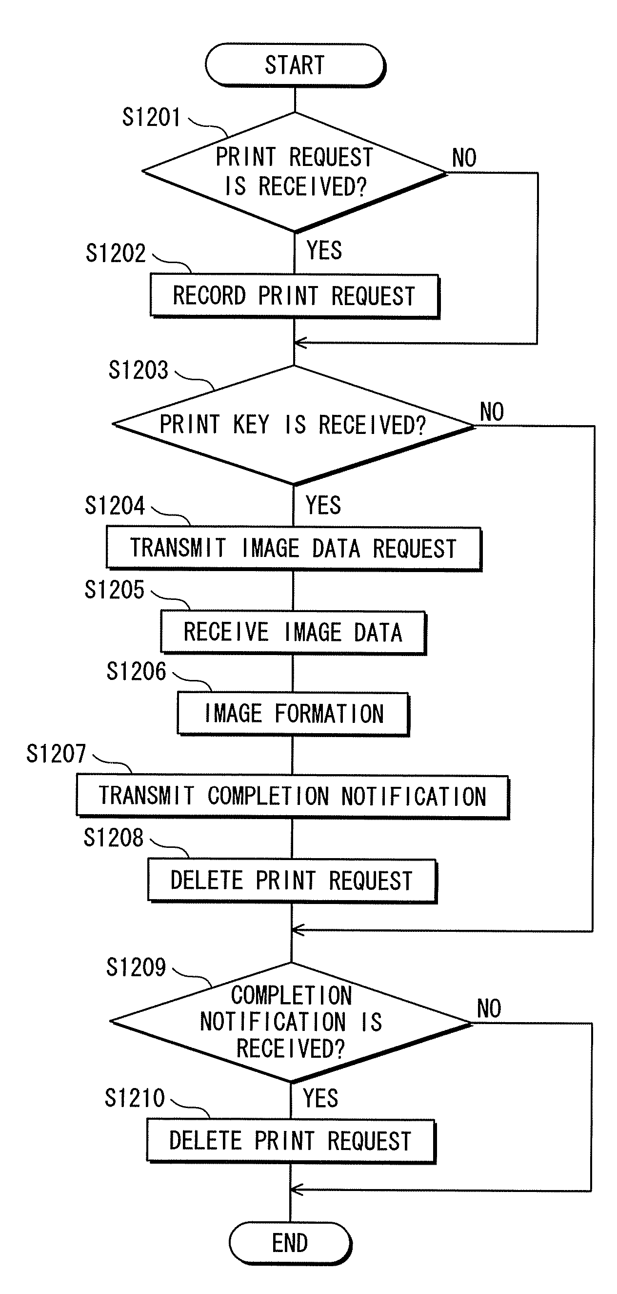
[0070]Firstly, a data structure of communication data of the second embodiment will be described. FIG. 9 shows the communication data structure of the second embodiment. As shown in FIG. 9, the communication data structure of the second embodiment includes a field of a print key instead of the two fields of the user ID and the image data name.

[0071]The print key is a five-digit number that is generated by a printer driver to display when a user makes a print request in a personal computer.

[0072]Because the other fields are same as in the first embodiment, the explanations thereof are omitted.

(2) Operation of Person...


PUM


Abstract

After a print request is made from a personal computer to a multifunction peripheral, when a user who logs into the multifunction peripheral instructs an execution of the print request in the multifunction peripheral, the multifunction peripheral requests the personal computer to transmit image data. Then, the personal computer transmits the requested image data to the multifunction peripheral. The multifunction peripheral executes the printing using the received image data. When the printing is completed, the multifunction peripheral transmits a completion notification indicating that the printing is completed to the personal computer. When receiving the completion notification, the personal computer transmits a completion notification having the same content as the received completion notification to the multifunction peripheral.

Description

CROSS REFERENCE TO RELATED APPLICATIONS[0001]This application is based on application No. 2007-137952 filed in Japan, the contents of which are hereby incorporated by reference.BACKGROUND OF THE INVENTION[0002](1) Field of the Invention[0003]The present invention relates to an image processing system, and especially to an image processing system that can achieve a good balance between security protection and a user's convenience in a case of pull print.[0004](2) Related Art[0005]In recent years, a network printer has been widely used, and the following method of using the network printer has become common. In an office environment, a plurality of multifunction peripherals (MFP) are connected to a network in order to print document data and the like that is made by and transmitted from a personal computer (PC). In this case, if a user tries to print a document in an unfamiliar office environment such as a business trip destination, the user's convenience is reduced because it is diff...

Claims


Application Information

Patent Timeline
Patent Type & Authority Applications(United States)
IPC IPC(8): G06F15/00
CPCG06F3/1222G06F3/1238G06F3/1285G06F21/608H04N1/00204H04N1/00408H04N1/00413H04N1/00482H04N1/32771H04N1/32776H04N1/4413H04N2201/0018H04N2201/0039H04N2201/0075H04N2201/0094
Inventor TAKAHASHI, KENICHIKITAMURA, MASAHIROIWAKI, MITSUZOSAKIYAMA, DAISUKE
Owner KONICA MINOLTA BUSINESS TECH INC
Why Eureka
Try Eureka