
Method for allocating storage area to virtual volume

a technology for virtual volume and storage area, applied in the direction of memory address/allocation/relocation, input/output to record carriers, instruments, etc., can solve the problems of increasing the volume of data to be handled by the computer, increasing the burden on management and higher costs, and unable to ensure the necessary storage capacity, so as to achieve the effect of effectively allocating storage area to the computer

Inactive Publication Date: 2006-05-18
HITACHI LTD
View PDF19 Cites 28 Cited by
  • Summary
  • Abstract
  • Description
  • Claims
  • Application Information

AI Technical Summary

Benefits of technology

[0006] However, if a plurality of computers are coupled to the storage system, it is necessary to add the software to all of such computers, and further, if such plurality of computers differ in their types, software associated with each type must be installed. Furthermore, when an operating system used for a computer is upgraded, it is necessary to update associating software, following the upgrade of the OS version. Accordingly, pre-installing software for the purpose of allowing the computer to recognize the size extension of a storage area results in increased management burdens and higher costs.
[0010] According to the present invention, a storage area can be effectively allocated to a computer.

Problems solved by technology

Accordingly, pre-installing software for the purpose of allowing the computer to recognize the size extension of a storage area results in increased management burdens and higher costs.
Now, the reason why the size of a storage area allocated to a computer is that data volume to be handled by the computer will increase and the necessary storage capacity will not be ensured by the initially allocated storage area.
With such arrangement, however, when the computer is not using such a large volume of data, a free area will occur in the storage area allocated to the computer, thus causing a wasted storage area.

Method used


Image

  • Method for allocating storage area to virtual volume
  • Method for allocating storage area to virtual volume
  • Method for allocating storage area to virtual volume

Examples


first embodiment

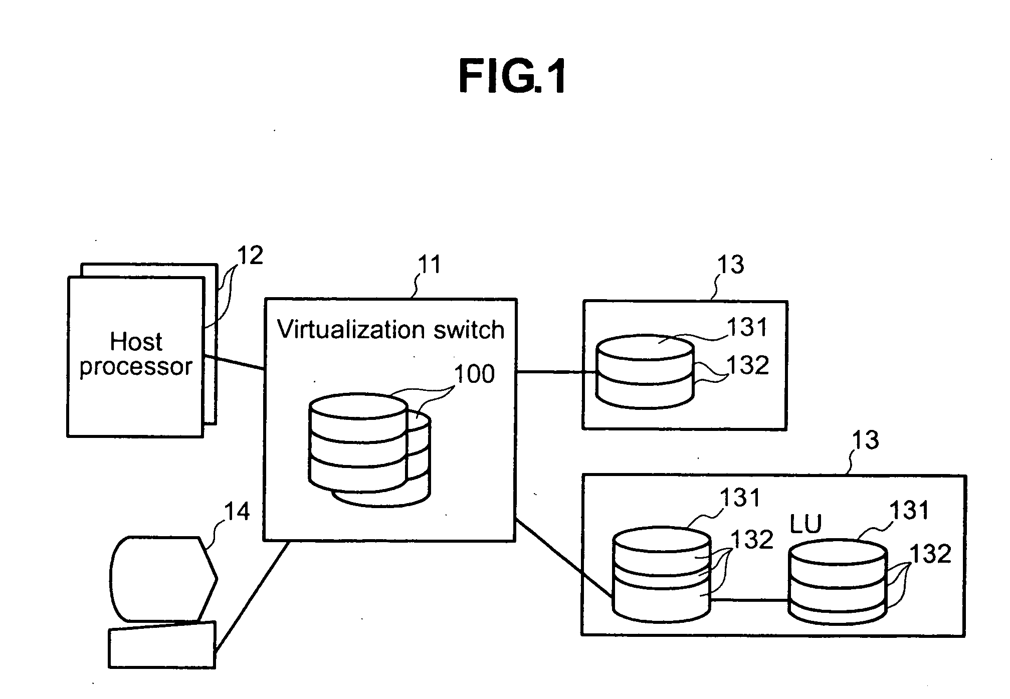
[0022]FIG. 1 is a diagram showing an example of overall configuration of a system to which the present invention is applied.

[0023] The system comprises at least one host processor 12, at least one storage device 13, a virtualization switch 11 and a management console 14.

[0024] The host processor 12 is a computer that uses data stored in the storage device 13. The host processor 12 may be a file server, which has a function to provide other computers that are not coupled to the virtualization switch 11 with a storage area provided by the virtualization switch 11.

[0025] The storage device 13 is a storage unit or a storage system. Here, a storage device shall imply a single storage device such as a hard disk or a DVD drive, and a storage system shall imply a storage sub-system which has a control unit or a disk device or disk devices such as one or a plurality of hard disk drives that are coupled to the control unit, and the control unit controls inputs and outputs to each disk devi...

second embodiment

[0064] Next, a second preferred embodiment according to the present invention will be described.

[0065] With the first embodiment, no consideration is given to a case where the real region 132 is first allocated to a virtual volume, and then the data stored in the real region 132 will not be used anymore. In this connection, in the second embodiment, consideration will be given to an arrangement, in addition to the arrangement employed in the first embodiment, in which allocation of the real region 132 that is not used any more to the virtual volume 100 will be ceased (hereinafter referred to as “released”).

[0066] In the embodiment, a defrag processing program 214 is stored in the memory of the control unit 210, in addition to the configuration of the first embodiment. The control unit 210 receives a defrag initiation instruction issued by the system administrator via the management console 14, executes the defrag processing program 214 to re-arrange data such as files stored in th...

third preferred embodiment

[0075] Next, a third preferred embodiment according to the present invention will be described.

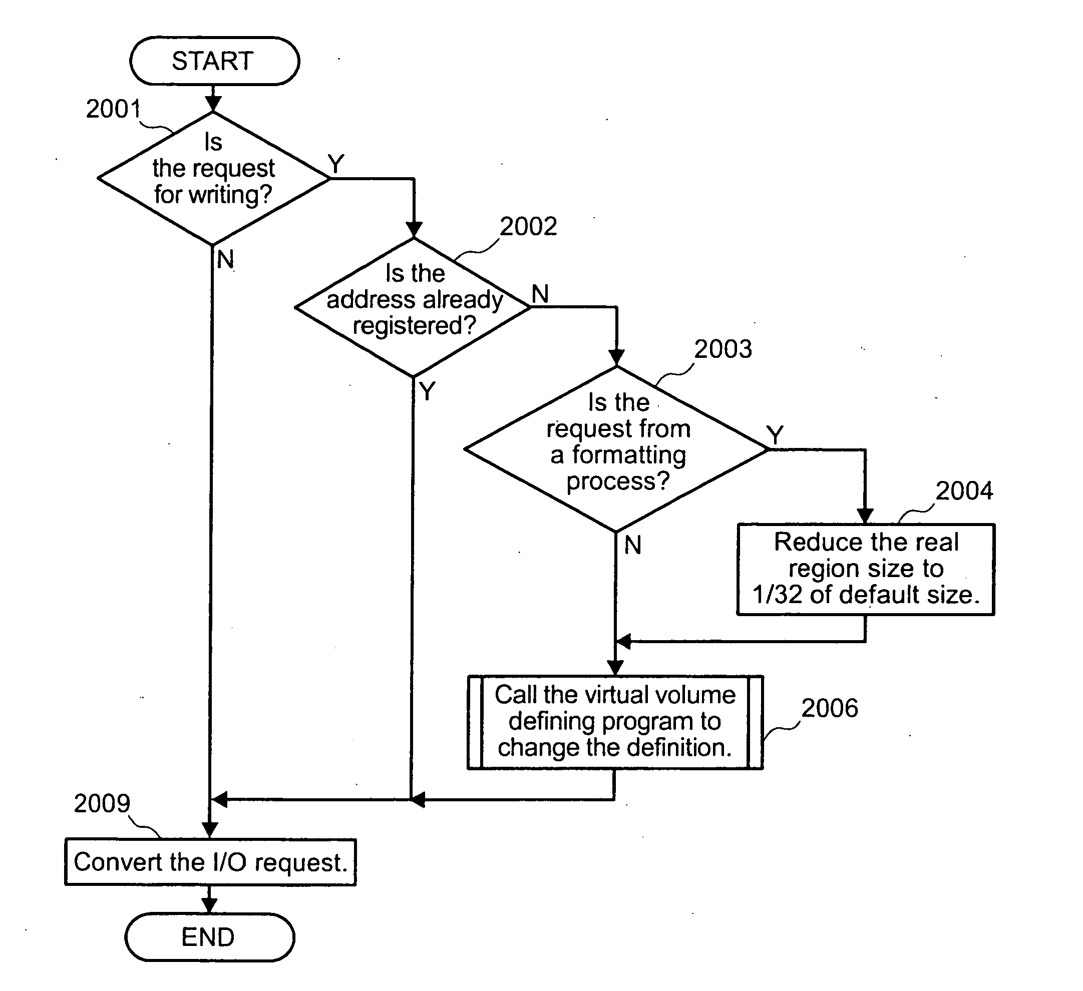
[0076] In the first embodiment, the size of the real region 132 to be allocated to the virtual volume 100 is fixed. However, for the request for writing data based on a predetermined process, e.g., formatting process, a writing process that uses a comparatively small portion of a storage area will occur. When the fixed-size real region 132 is allocated to the virtual volume 100 as is the case in other embodiments, there will be waste in the allocated storage area. Taken the above into consideration, in the embodiment, the real region 132 that is appropriate to the process will be allocated to the virtual volume 100.

[0077] In the embodiment, in addition to the configuration of the first embodiment, a format processing program 215 is stored in the memory of the control unit 210. In addition, the entry 317 of the virtual volume management table 221 contains information indicating the size o...


PUM


Abstract

In a system where a storage device is coupled to a computer, a storage area in the storage device is efficiently allocated to the computer. The system comprises a virtualization apparatus to be coupled to the computer and a plurality of storage devices to be coupled to the virtualization apparatus. The virtualization apparatus, responding to a request from the computer, issues a notice to the effect that a predetermined size of virtual volume has been allocated to the computer. The virtualization apparatus, upon receiving an access request from the computer to the virtual volume, allocates storage areas existing in a plurality of storage devices to the virtual volume, converts the access request received from the computer to an access request addressed to a storage device having the storage devices allocated to the virtual volume, and transmits the converted access request to the storage device.

Description

BACKGROUND OF THE INVENTION [0001] The present invention refers to a technique for allocating a storage area of a storage system to a computer. [0002] The switch that integrates a plurality of storage areas of a plurality of storage systems and allows them to access a computer as one storage area is disclosed in a patent document 1. According to the patent document 1, the switch is coupled to a plurality of storage systems and a host. The switch receives an access request from the host to an integrated logical unit comprising a plurality of storage areas (logical units) of the plurality of storage systems. Thereafter, the switch converts the access request received to an access request to a logical unit in which data to be accessed is stored, and transmits the access request thus converted to a storage system that has the logical unit. [0003] On the other hand, a software technique, which, when the logical storage area allocated to a computer is extended, recognizes the extension of...

Claims


Application Information

Patent Timeline
Patent Type & Authority Applications(United States)
IPC IPC(8): G06F12/00G06F12/08G06F3/06
CPCG06F3/0608G06F3/0631G06F3/0665G06F3/0683
Inventor SERIZAWA, KAZUYOSHIMORITA, SHINJIIWAMI, NAOKO
Owner HITACHI LTD
Learn More