Projection lens device and projection display apparatus using the same
a projection lens and projection display technology, applied in the field of projection lens devices and projection display apparatuses, can solve the problems of increasing manufacturing costs, the concept of inserting reflective elements, etc., and achieve the effects of wide angle of view, high projection performance, and long back focal length
- Summary
- Abstract
- Description
- Claims
- Application Information
AI Technical Summary
Benefits of technology
Problems solved by technology
Method used
Image

Examples
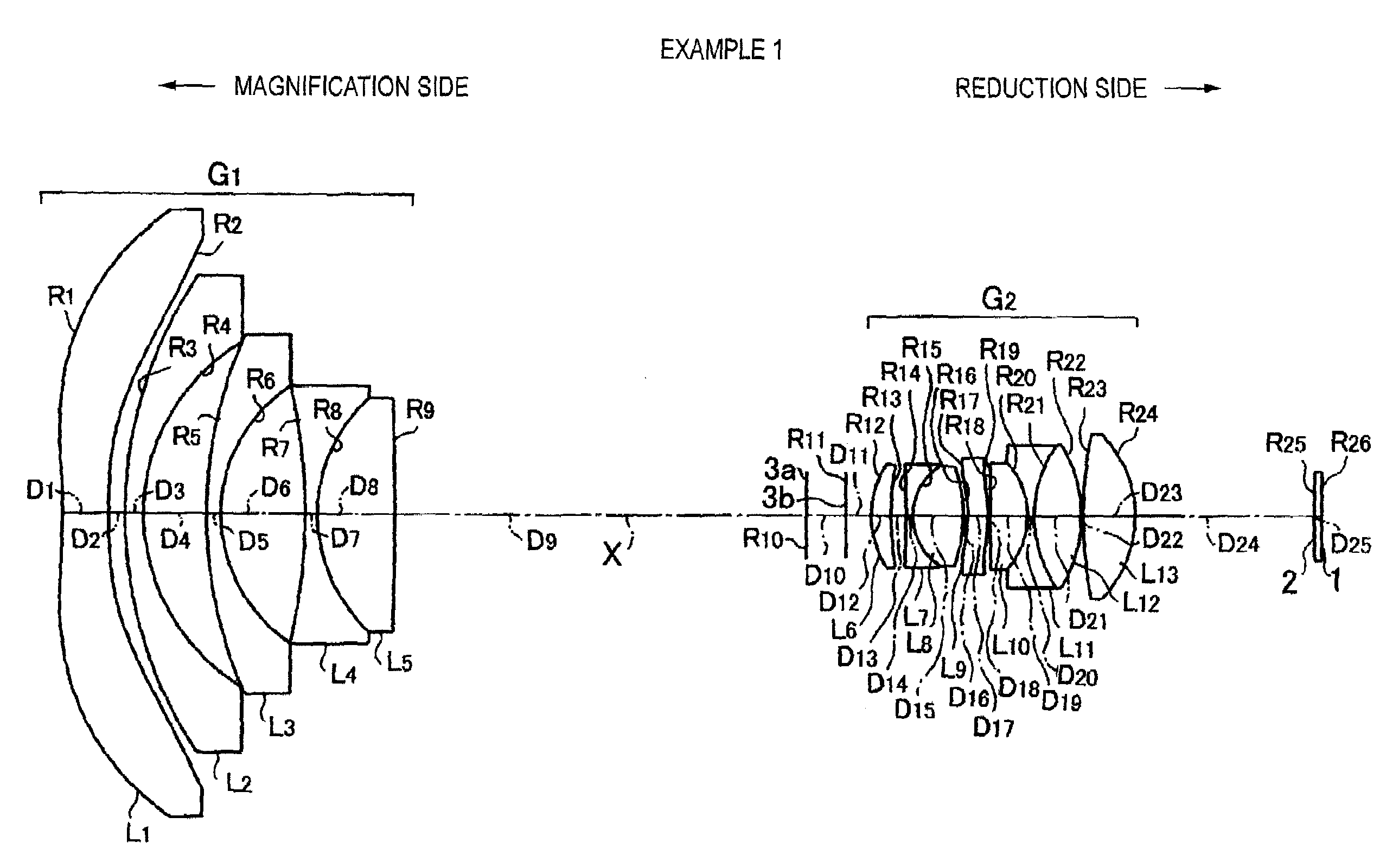
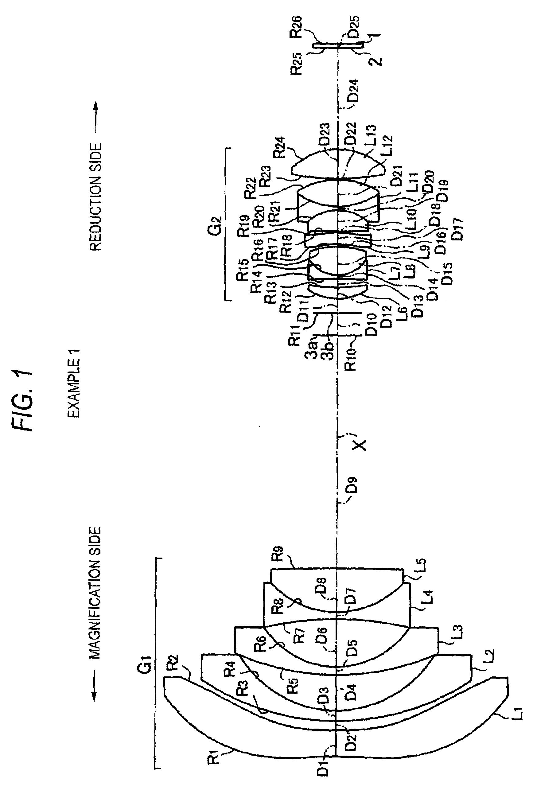
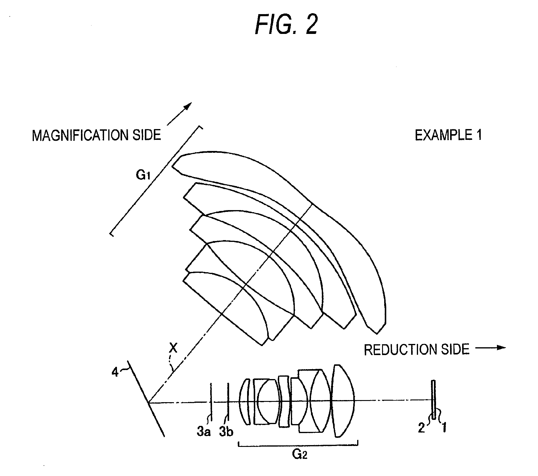
example 1
[0102]As shown in FIG. 1, the projection lens device according to Example 1 includes, in order from a magnification side, a first lens group G1 having a negative refractive power, a mask 3a and an aperture diaphragm 3b, and a second lens group G2 having a positive refractive power. The projection lens device is substantially telecentric on a reduction side thereof. Also, FIG. 2 illustrates the configuration in which a reflection mirror 4 serving as an optical-path deflecting unit that deflects an optical path is disposed between the first lens group G1 and the second lens group G2 in the projection lens device shown in FIG. 1.
[0103]The first lens group G1 includes, in order from the magnification side, a first lens L1 formed of an aspheric lens having a low refractive power, second and third lenses L2, L3 formed of negative meniscus lenses having concave surfaces directed to the reduction side, and a two-element cemented lens formed by cementing a fourth lens L4 formed of a biconcav...
example 2
[0117]The configuration of a projection lens device according to Example 2 is shown in FIG. 3, and is similar to the projection lens device according to Example 1 in that a first lens group G1 having a negative refractive power, aperture diaphragms (masks) 3a and 3b, and a second lens group G2 having a positive refractive power are arranged in order from a magnification side, and the projection lens device is substantially telecentric on a reduction side thereof.
[0118]The first lens group G1 includes, in order from the magnification side, a first lens L1 formed of an aspheric lens having a low refractive power, a second lens L2 and a third lens L3 which are formed of negative meniscus lenses having concave surfaces directed to the reduction side, a fourth lens L4 formed of a biconcave lens, a three-element cemented lens formed by sandwiching a sixth lens L6 formed of a biconvex lens between a fifth lens L5 and a seventh lens L7 which are formed of negative lenses, and an eighth lens...
example 3
[0123]The configuration of a projection lens device according to Example 3 is shown in FIG. 4. In the projection lens device, there are arranged, in order from a magnification side, a first lens group G1 having a negative refractive power, and a second lens group G2 having a positive refractive power. The projection lens device is substantially telecentric on a reduction side thereof. Also, a space between the first lens group G1 and the second lens group G2 is set as the maximum inter-lens space (the maximum air space). In addition, FIG. 5 illustrates the configuration in which a reflection mirror 4 serving as an optical-path deflecting unit for deflecting an optical path is disposed between the first lens group G1 and the second lens group G2 of the projection lens device shown in FIG. 4.
[0124]The first lens group G1 includes, in order from the magnification side, a first lens L1 formed of an aspheric lens having a low refractive power, a second lens L2 and a third lens L3 which a...
PUM
 Abstract
Description
Claims
Application Information
 - R&D Engineer
- R&D Manager
- IP Professional
- Industry Leading Data Capabilities
- Powerful AI technology
- Patent DNA Extraction
Browse by: Latest US Patents, China's latest patents, Technical Efficacy Thesaurus, Application Domain, Technology Topic.
© 2024 PatSnap. All rights reserved.Legal|Privacy policy|Modern Slavery Act Transparency Statement|Sitemap