Step-down switching regulator with freewheeling diode

a switching regulator and diode technology, applied in the direction of dc-dc conversion, climate sustainability, power conversion systems, etc., can solve the problems of significant and unwanted off-state leakage current, schottky diodes, and low power dissipation in the switch, and achieve high dv/dt and voltage overshoot, and high gate drive loss

Active Publication Date: 2008-11-27
ADVANCED ANALOGIC TECHNOLOGIES INCORPORATED
View PDF5 Cites 37 Cited by
  • Summary
  • Abstract
  • Description
  • Claims
  • Application Information

AI Technical Summary

Benefits of technology

The technical effect of this patent is to provide an improved design for regulating power in electronic devices. Current methods like buck and synchronous buck have issues with efficiency, noise, and instability. This new method uses a different approach called step-down which solves some of these problems by reducing certain factors like rectifier switches and conductivity loss. Overall, this change will make it easier to control power levels in electronics without causing any negative side effects.

Problems solved by technology

The technical problem addressed in this patent text is to improve the efficiency and minimize the loss of power in a synchronous buck converter by reducing the on-time of the synchronous rectifier MOSFET and the negative going voltage trans of the inductor current. However, the traditional method of removing the rectifier diode from the converter results in poor energy efficiency and excessive noise. The patent text also discusses the issue of unclamped inductive switching and the effect of breakdown voltage on the on-time of the high-side MOSFET. The text also describes the tradeoff between the on-time and off-load current in a circuit design.

Method used


Image

  • Step-down switching regulator with freewheeling diode
  • Step-down switching regulator with freewheeling diode
  • Step-down switching regulator with freewheeling diode

Examples


Embodiment Construction

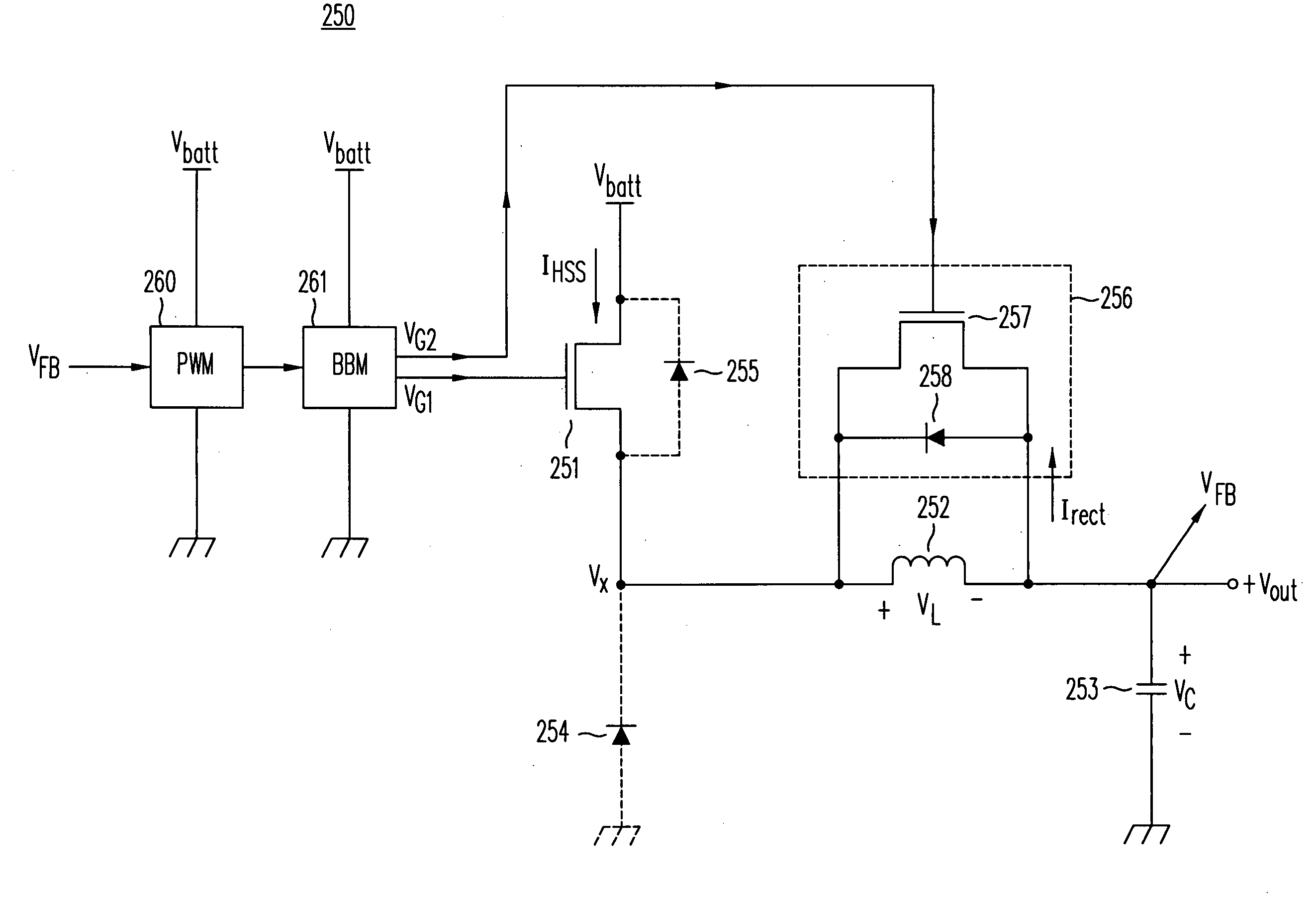
[0107]FIG. 6 illustrates one embodiment of the freewheeling step-down converter and switching voltage regulator made in accordance with this invention. As shown, converter 250 comprises a high-side power MOSFET 251, an inductor 252, an output capacitor 253, a freewheeling clamp 256 comprising a diode 258 and a freewheeling power MOSFET 257, break-before-make (BBM) circuitry 261 and a pulse-width modulation (PWM) controller 260. Using feedback VFB from the output terminal of converter 250, operation of PWM controller 260 controls the on-time of MOSFETs 251 and 257 to regulate a specified output voltage VOUT. Feedback circuitry for DC / DC converters is well known in the art and is described, for example, in application Ser. Nos. 11 / 890,818, titled “High-Efficiency DC / DC Voltage Converter Including Down Inductive Switching Pre-Regulator And Capacitive Switching Post-Converter,” and Ser. No. 11 / 890,956, titled “High-Efficiency DC / DC Voltage Converter Including Up Inductive Switching Pre-...


PUM


Abstract

A freewheeling DC/DC step-down converter includes a high-side MOSFET, an inductor and an output capacitor connected between the input voltage and ground. A freewheeling clamp, which includes a freewheeling MOSFET and diode, is connected across the inductor. When the high-side MOSFET is turned off, a current circulates through the inductor and freewheeling clamp rather than to ground, improving the efficiency of the converter. The converter has softer diode recovery and less voltage overshoot and noise than conventional Buck converters and features unique benefits during light-load conditions.

Description


Claims


Application Information

Patent Timeline
Owner ADVANCED ANALOGIC TECHNOLOGIES INCORPORATED
Why Eureka
Try Eureka