Image forming apparatus and process unit
- Summary
- Abstract
- Description
- Claims
- Application Information
AI Technical Summary
Benefits of technology
Problems solved by technology
Method used
Image
Examples
first embodiment
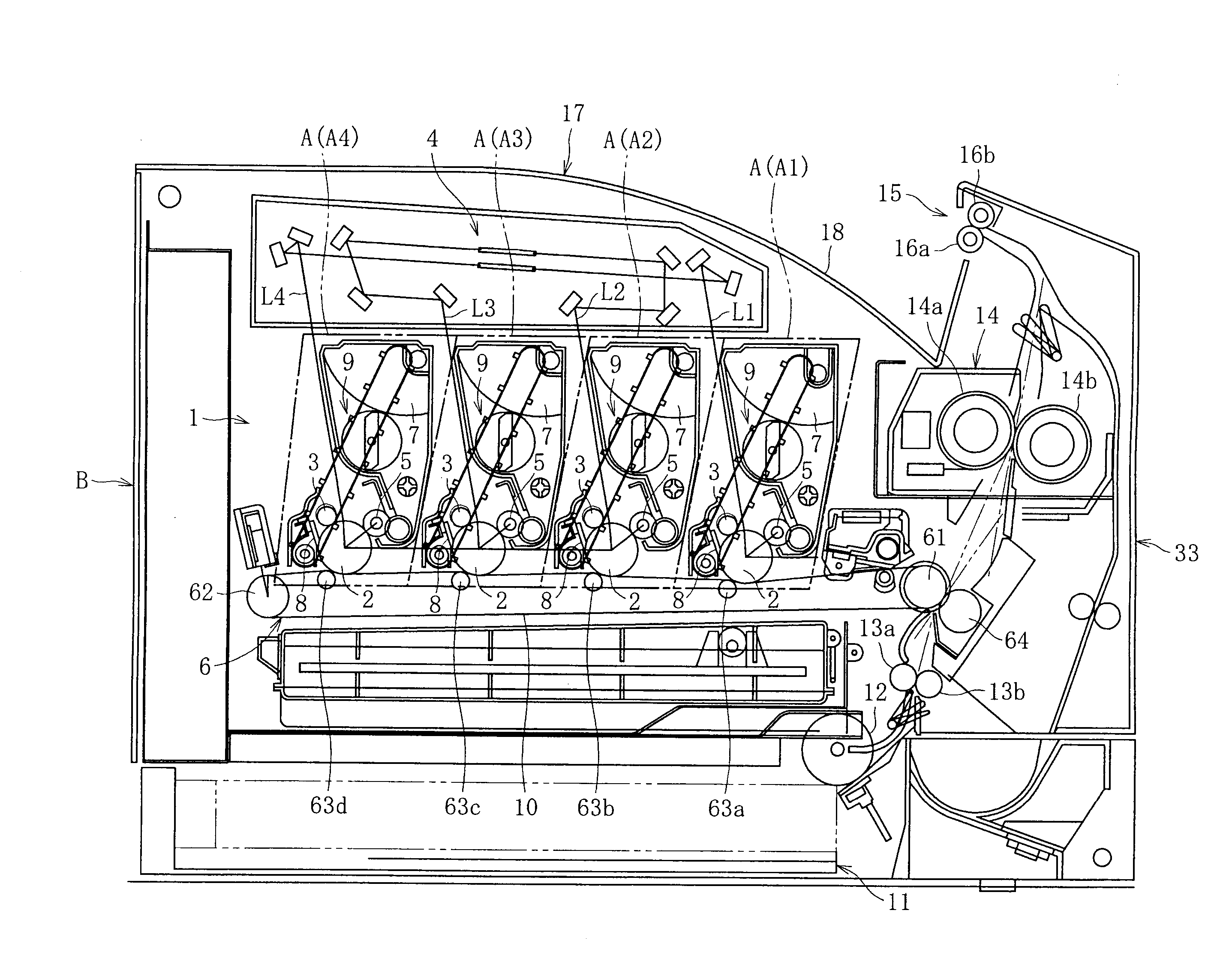
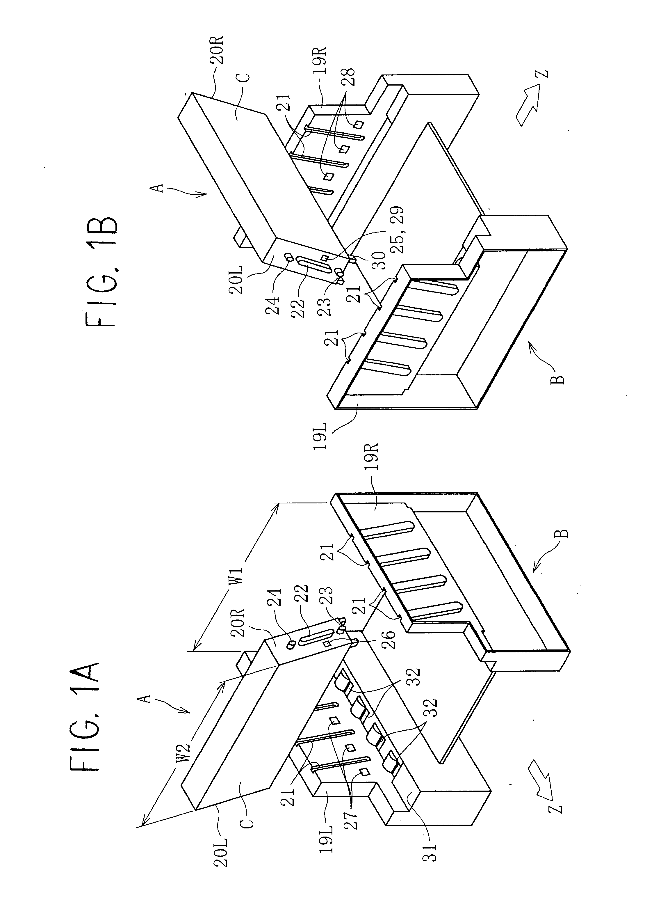
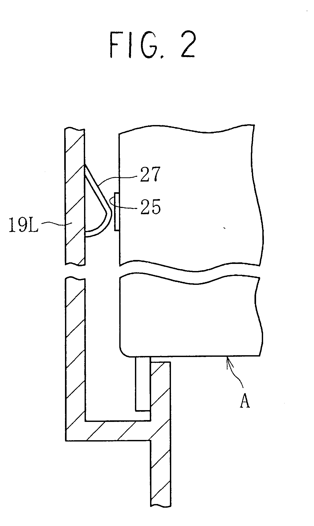
[0068]FIG. 7 shows the present invention and shows the left end of the process unit A and the main apparatus body B. As shown in this Figure, in the insertion hole 32, there is provided an engagement section 32a that engages with the convex section 30 of the process unit A; in this case, the engagement section 32a is formed on a straight section that extends in the vertical direction facing the left side plate 19L. The top of the engagement section 32a is linked with a guidance section 32b that is inclined towards the left side plate 19L (in other words, approaches the left side plate 19L more closely, going downwards), and the top end of this guidance section 32b reaches the aperture of the insertion hole 32.
[0069]Also, on the convex section 30 of the process unit A, there is provided a straight section 30a extending in the vertical direction facing the opposite side to the left side plate 19L; the bottom of this straight section 30a is linked with a guidance section 30b that is in...
second embodiment
[0070]FIG. 8 shows the present invention. In this case, the straight section 30a that extends in the vertical direction facing the opposite side to the left side plate 19L is formed at the convex section 30 of the process, unit A, reaching its tip. In other words, no inclined guidance section 30b as in FIG. 7 is formed. Also, a straight section 32a and guidance section 32b are provided in the same way as in the case of FIG. 7 in the insertion hole 32.
third embodiment
[0071]FIG. 9 shows the present invention. In this embodiment, in the insertion hole 32, there is performed an engagement section 32a (straight section) that extends in the vertical direction facing the left side plate 19L, reaching the aperture thereof: no inclined guidance section 32b as in FIG. 7 is formed. Also, a straight section 30a and guidance section 30b are provided on the convex section 30, in the same way as in the case of FIG. 7.
[0072]In FIGS. 7 to 9, even in the case where the process unit A is offset to the maximum (whether approaching this or in contact therewith) towards the right side plate, not shown, between the two side plates, the bottom end P1 of the guidance section 32b of the convex section 30 or the bottom end P1 of the straight section 30a with no guidance section 30b is arranged more separated with respect to the left side plate 19L than the top end P2 of the guidance section 32b of the insertion hole 32 or the top end P2 of the straight section 32a with n...
PUM
 Abstract
Description
Claims
Application Information
 - R&D
- Intellectual Property
- Life Sciences
- Materials
- Tech Scout
- Unparalleled Data Quality
- Higher Quality Content
- 60% Fewer Hallucinations
Browse by: Latest US Patents, China's latest patents, Technical Efficacy Thesaurus, Application Domain, Technology Topic, Popular Technical Reports.
© 2025 PatSnap. All rights reserved.Legal|Privacy policy|Modern Slavery Act Transparency Statement|Sitemap|About US| Contact US: help@patsnap.com


