Unlock instant, AI-driven research and patent intelligence for your innovation.

Imaging system

Active Publication Date: 2008-11-27
TECHNISCAN +2
View PDF74 Cites 28 Cited by
  • Summary
  • Abstract
  • Description
  • Claims
  • Application Information

AI Technical Summary

Benefits of technology

[0016]The present invention provides techniques for imaging the internal structures of an object using an acoustic wave field. In one aspect, for example, a method of imaging internals of a physical object using acoustic waves may include transmitting an acoustic wave field toward the object, receiving a resultant acoustic wave field with a receiver, where the resultant acoustic wave field is in response to the transmitted acoustic wave field reflected from or transmitted through the object, and determining a predicted resultant acoustic wave field derived from a model of the object. The method may also include determi

Problems solved by technology

Non-uniformities can result in attenuation, varying propagation speed, reflection, refraction, and scattering of the acoustic waves passing through the object.
The current standard of care has significant problems, generating unacceptably high rates of false positive tests—between 8% and 10%—and upwards of 15% false negative tests.
The result is that many women suffer from unnecessary and invasive biopsies.
In addition, each year the U.S. healthcare system spends an estimated $2.1 billion on biopsies, which yield negative results more than 75% of the time.
When breast cancer cells reach the axillary (underarm) lymph nodes, they may continue to grow, often causing the lymph nodes in that area to swell.
Fibrocystic changes can cause breast swelling and pain.
Although widespread use of screening mammography has increased the number of breast cancers found before they cause any symptoms, some breast cancers are not found by mammography, either because the test was not done or because even under ideal conditions mammography cannot find every breast cancer.
It has difficulty imaging objects with low reflectivity or high absorption of sound.
It produces images which are typically two-dimensional, distorted, grainy, and contain speckle.

Method used


Image

  • Imaging system
  • Imaging system
  • Imaging system

Examples


Embodiment Construction

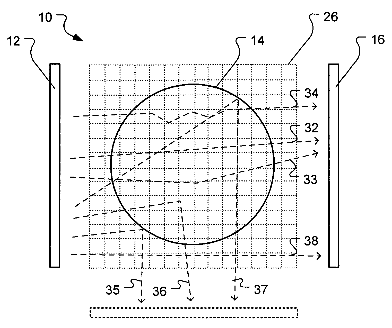
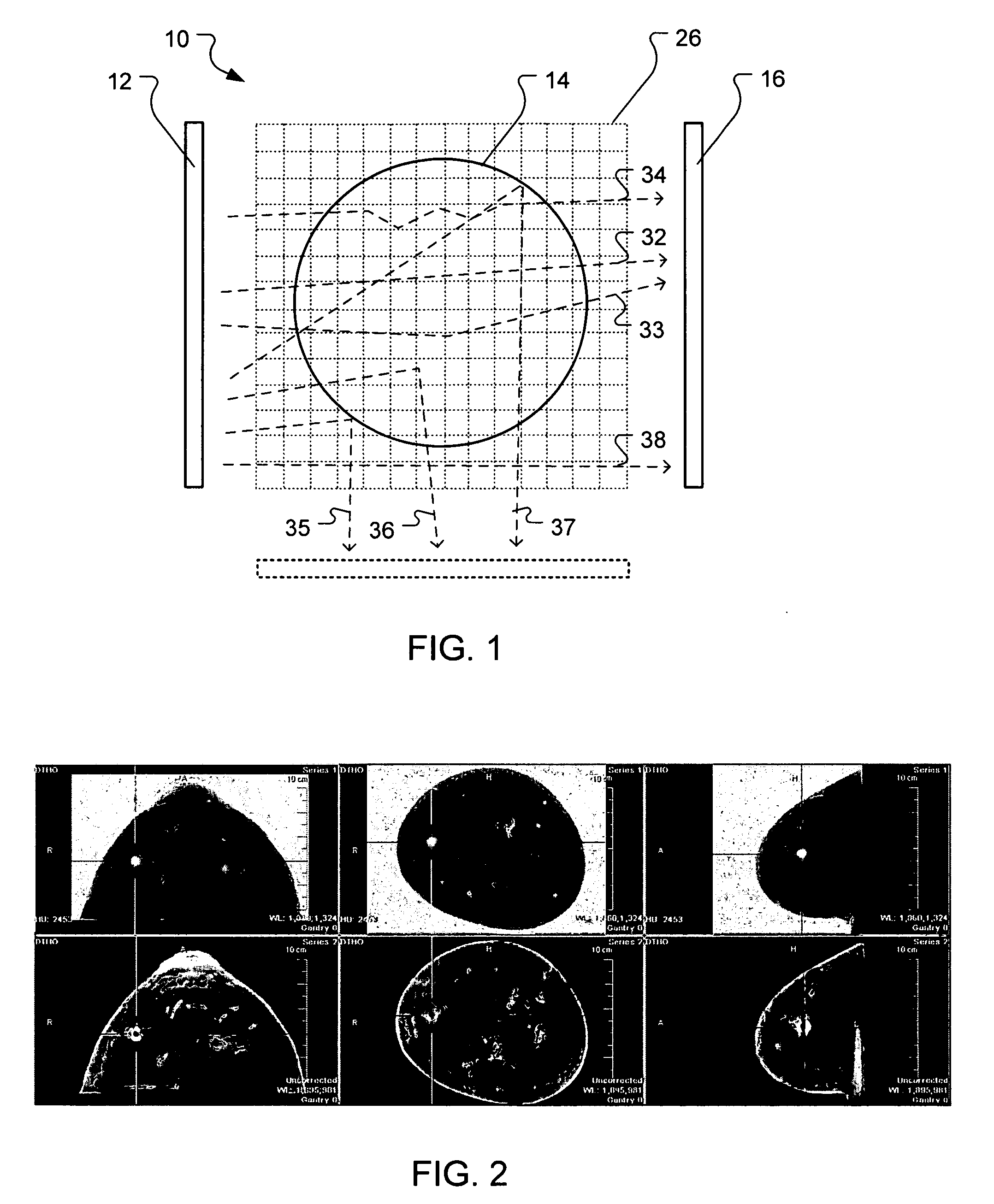
[0042]The present invention provides techniques for utilizing acoustic wave fields to image internal structures of physical objects. In one aspect, for example, a method of imaging internals of a physical object using acoustic waves may include transmitting an acoustic wave field toward the object, receiving a resultant acoustic wave field with a receiver, wherein the resultant acoustic wave field is in response to the transmitted acoustic wave field reflected from or transmitted through the object, and determining a predicted resultant acoustic wave field derived from a model of the object. The method may further include determining a residual between the predicted resultant acoustic wave field and the resultant acoustic wave field, and back propagating the residual to determine corrections to the model of the object. Additional aspects may include iterating the steps of transmitting an acoustic wave field, receiving a resultant acoustic wave field, determining a predicted resultan...


PUM


Abstract

Methods for imaging the internal structures of an object using an acoustic wave field are provided. In one aspect, for example, a method of imaging internals of a physical object using acoustic waves may include transmitting an acoustic wave field toward the object, receiving a resultant acoustic wave field with a receiver, where the resultant acoustic wave field is in response to the transmitted acoustic wave field reflected from or transmitted through the object, and determining a predicted resultant acoustic wave field derived from a model of the object. The method may also include determining a residual between the predicted resultant acoustic wave field and the resultant acoustic wave field, and back propagating the residual to determine corrections to the model of the object. In another aspect, the above recited steps may be further iterated to successively refine the model of the object over a number of iterations until a predefined condition is reached.

Description

PRIORITY DATA[0001]This application claims the benefit of U.S. Provisional Patent Application Ser. Nos. 60 / 930,413 and 60 / 930,377, both filed on May 15, 2007, and both of which are incorporated herein by reference in their entireties.BACKGROUND OF THE INVENTION[0002]1. Field of the Invention[0003]The present invention relates generally to acoustic imaging systems.[0004]2. Related Art[0005]Various imaging techniques for imaging inside objects are known. For example, x-ray and magnetic resonance imaging has found use as a medical diagnosis tool. It is also known that acoustic waves can be propagated through objects. When an acoustic wave propagates through a non-homogenous object, it is affected by spatial variations in the stiffness, density and absorption of the object. Non-uniformities can result in attenuation, varying propagation speed, reflection, refraction, and scattering of the acoustic waves passing through the object. By transmitting an acoustic wave into the object, and me...

Claims


Application Information

Patent Timeline
IPC IPC(8): A61B8/00
CPCA61B8/0825G01S15/8977G01S7/52036A61B8/58A61B8/4494A61B8/15A61B8/4477A61B8/4483
Inventor JOHNSON, STEVEN A.BORUP, DAVID T.WISKIN, JAMES W.
Owner TECHNISCAN