
Apparatus and method for imaging objects with wavefields

a wavefield and apparatus technology, applied in the field of apparatus and methods for imaging objects with wavefields, can solve the problems of reducing the effectiveness of the imaging program, traumatic patient biopsy, and ten-fold more expensive biopsy, so as to eliminate the need for mechanical rotation and enhance system performance

Inactive Publication Date: 2010-11-30
TECHNISCAN
View PDF26 Cites 63 Cited by
  • Summary
  • Abstract
  • Description
  • Claims
  • Application Information

AI Technical Summary

Benefits of technology

This method enhances diagnostic accuracy by providing high-resolution images that can differentiate between cancerous and benign tissues, reducing the need for biopsies and improving early detection of breast cancer, while also addressing limitations in dense breast tissue imaging.

Problems solved by technology

In the prior art the presence of this layering or porosity has greatly diminished the effectiveness of the imaging program.
Even when mammography and ultrasound are used together, the specificity for discriminating between cancer and fibrocystic condition or between cancerous tumor and a fibroadenoma is not high enough to eliminate the need for biopsy in 20 to 30 percent of lesions.
However, biopsy of benign lesions is traumatic to the patient and expensive.
A mammogram costs about $90 but a biopsy is about ten times more expensive.
Inverse scattering easily discriminates fat from other tissues, while mammography and present clinical ultrasound cannot.
A traditional problem with inverse scattering imaging is the long computing times required to make an image.
Diffraction Tomography is extremely rapid in image computation, but suffers the fatal flaw for medical imaging of producing images that are blurred and not of acceptable quality for diagnostic purposes and it is not quantitatively accurate.
However, making a full 3-D image with a 3D algorithm or even from several, stacked 2-D image slices made with a 2D algorithm would have required computing speed not available then and only becoming available now.
However, EIT has poor spatial resolution.
Work on making 3-D EIT images is less developed because of the increased computer run time of 3-D algorithms.
Another problem is the accumulated ionizing radiation dose over years of mammography.
However, if mammograms are taken every year from age 40 or earlier, by age 60 to 70 the accumulated dose begins to cause breast cancer.
Mammography is not useful in many younger women (because of the tendency for greater breast density) or older women with dense breasts (such as lactating women).
About 15 percent of women have breasts so dense that mammography has no value and another 15 percent of women have breasts dense enough that the value of mammography is questionable.
Thus 30 percent of all mammograms are of questionable or zero value because of image artifacts from higher than normal breast density.

Method used


Image

  • Apparatus and method for imaging objects with wavefields
  • Apparatus and method for imaging objects with wavefields
  • Apparatus and method for imaging objects with wavefields

Examples


example 1

Acoustic Scattering—Scalar Model Equations

[0136]This first example is designed to give the basic structure of the algorithm and to point out why it is so fast in this particular implementation compared to present state of the art. The background medium is assumed to be homogeneous medium (no layering). This example will highlight the exploitation of convolutional form via the FFT, the use of the Frechet derivative in the Gauss-Newton and FR—RP algorithms, the use of the biconjugate gradient algorithm (BCG) for the forward problems, the independence of the different view, and frequency, forward problems. It will also set up some examples which will elucidate the patent terminology. The field can be represented by a scalar quantity f. The object is assumed to have finite extent The speed of sound within the object is c=c(x). The speed of sound in the background medium is the constant co. The mass density is assumed to be constant. The attenuation is modelled as the imaginary part of t...

example 5

Extension to Biot Theory (Acoustic Approximation)

[0270]In the article [Boutin, 1987, Geophys. J. R. astr. Soc., vol. 90], herein incorporated by reference, a greens function for the determination of a point response to a scattering point located in an isotropic, homogeneous, porous medium that supports elastic waves is developed. The implementation of this Greens' function into an imaging algorithm has never been carried out before. In this section, we have adapted their approach to derive an acoustic approximation to the fully elastic Biot theory that enables us to present a simplified practical tool for the imaging of porosity-like parameters in a geophysical context. The implementation of the full elastic Biot imaging algorithm using the Green's function of [Boutin, 1987] in place of the one derived in [Wiskin, 1992] is no different from the discretization employed here. The use of the sinc basis functions, the FFT's, the biconjugate gradients, and so on, is identical.

[0271]We ha...

example 6

Non-Perturbative Inversion of Elastic Inhomogeneous Structures Buried Within a Layered Half Space

[0296]In elastic media (by convention in this patent, media that supports shear wave activity) the relevant parameters are γ, μ, (Lame′ parameters), ρ (density) and absorption. The inversion for these elastic parameters (i.e. the first and second Lame′ parameters, γ and μ follows virtually the same prescription as was outlined above for the acoustic scalar case. In a manner similar to the Electromagnetic Inversion problem discussed above, it is possible to break up the arbitrary 3 dimensional vector u(x,y,z), representing the displacement into components that propagate independently. The exact description of this procedure is given in [Wiskin, 1991], and [Muller, 1985]. This example will not deal with this decomposition since the idea behind this is more easily seen by looking at the electromagnetic example given earlier.

[0297]The idea here is to incorporate the above solution to the lay...


PUM

PropertyMeasurementUnit
transmission wave field imagingaaaaaaaaaa
speedaaaaaaaaaa
acoustic energyaaaaaaaaaa

Abstract

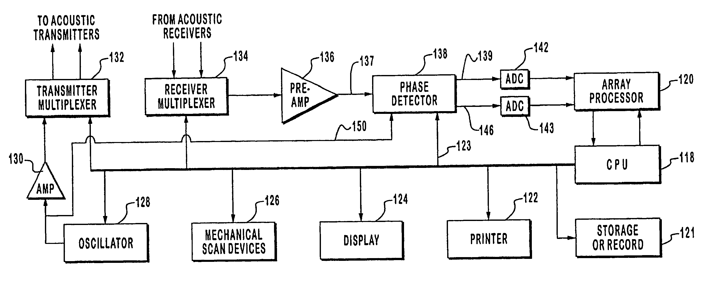
A transmission wave field imaging method, comprising the transmission of an incident wave field into an object, the incident wave field propagating into the object and, at least, partially scattering. Also includes the measuring of a wave field transmitted, at least in part, through an object to obtain a measured wave field, the measured wave field based, in part, on the incident wave field and the object. Additionally, the processing of the measured wave field utilizing a parabolic approximation reconstruction algorithm to generate an image data set representing at least one image of the object.

Description

PRIORITY CLAIM[0001]This is a continuation of U.S. patent application Ser. No. 10 / 615,569, filed Jul. 7, 2003, now U.S. Pat. No. 7,570,742 which is a continuation of U.S. patent application Ser. No. 10 / 024,035, filed on Dec. 17, 2001, now U.S. Pat. No. 6,636,584, which is a continuation of U.S. patent application Ser. No. 09 / 471,106, filed on Dec. 21, 1999, now U.S. Pat. No. 6,587,540, which is a continuation-in-part of U.S. patent application Ser. No. 08 / 706,205, filed on Aug. 29, 1996, now abandoned, which is a continuation-in-part of U.S. patent application Ser. No. 08 / 486,971, filed on Jun. 22, 1995, now abandoned; which are all herein incorporated by reference.INCORPORATION BY REFERENCE[0002]Material on one (1) compact disc accompanying this patent and labeled COPY 1, a copy of which is also included and is labeled as COPY 2, is incorporated herein by reference. The compact disc has a software appendix thereon in the form of the following three (3) files:[0003]Appendix A.txt, S...

Claims


Application Information

Patent Timeline
Patent Type & Authority Patents(United States)
IPC IPC(8): A61B5/00G01N23/00
CPCA61B5/0507A61B5/4312A61B8/00A61B8/463A61B5/7257A61B5/05A61B5/0536A61B8/485A61B8/0825
Inventor JOHNSON, STEVEN A.BORUP, DAVID T.WISKIN, JAMESBERGGREN, MICHAEL J.
Owner TECHNISCAN
Learn More