Shift Module

a technology of shift module and slider, which is applied in the direction of belt/chain/gearring, mechanical equipment, and gear control, etc., can solve the problems of high construction cost, easy wear and tear of above mentioned shift module, and high construction cost, so as to reduce the friction between the slider and the tappet, the effect of precise and friction-fr

Active Publication Date: 2008-12-04
FICO CABLES
View PDF10 Cites 3 Cited by
  • Summary
  • Abstract
  • Description
  • Claims
  • Application Information

AI Technical Summary

Benefits of technology

[0020]In a further preferred embodiment the tappet comprises a rotatably supported roller, at the end facing the slider. By means of this roller the friction between the tappet and the slider decreases. Thereby, the desired characteristic shift feeling can be adjusted more exactly and the wear-off is lower.
[0021]Preferably, the tappet is supported within a metal guide, which preferably is produced of powder metallic material. The metal guide in combination with the tappet preferably made of plastic material, enables a very exact and friction-free support of the tappet. Therefore, the wear-off is further decreased and the shift feeling is improved. Between the powder metallurgically produced material and the tappet, preferably consisting of a plastic material, a very frictionless bearing is enabled, having an almost constant friction behavior over the complete lifetime of the shift module.

Problems solved by technology

This construction is costly in manufacturing and comprises a plurality of mechanical components due to the two tappets, two springs and two micro switches.
The required shift ways, shift forces and the feeling during the shifting, particularly a haptic feedback for a successful change of gears is not adjustable over the total way of shifting or definable.
Additionally, the above mentioned shift modules are costly in construction and susceptible for wear off due to the use of return springs and stop members or the like.

Method used


Image

  • Shift Module
  • Shift Module
  • Shift Module

Examples


Embodiment Construction

[0057]In the following the preferred embodiments are discussed in detail with reference to the drawings.

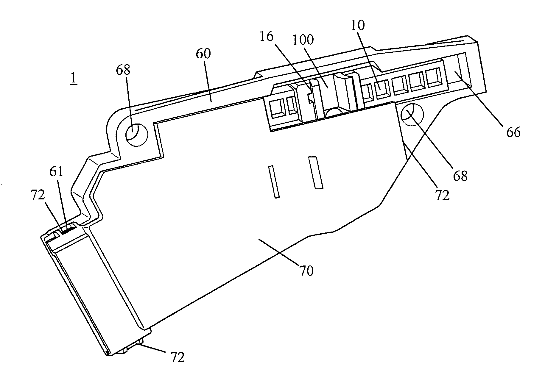
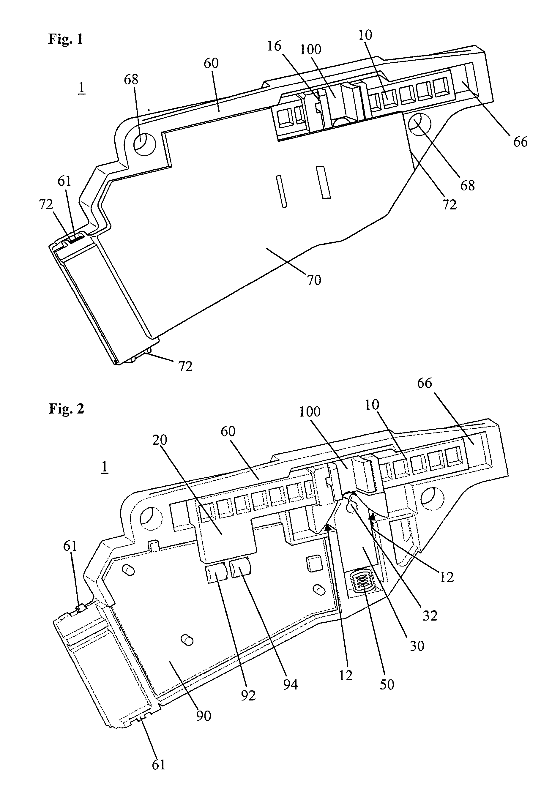
[0058]In FIG. 1 a shift module 1 is shown having a housing 60, a slider 10 and a housing lid 70. The shift module 1 is a relatively flat, compact part which can be mounted within a shift lever unit (not shown) of a motor vehicle. To this end the shift module 1 comprises mounting openings 68 in the housing 60, to be fixed within the shift lever unit by means of screws, rivets or the like.

[0059]The housing 60 is partially closed by means of a housing lid 70, to protect the inner components of shift module 1. For an easy assembly of the housing lid 70 at the housing 60, it is provided with clips 72, which engage corresponding projections 61 at the housing.

[0060]In FIG. 1 it is shown that the housing lid 70 leaves free an area over the slider 10, which comprises an actuation opening 16. Into this actuation opening 16 a projection 5 (see FIG. 22) of a shift lever (not shown) engages to...


PUM


Abstract

The present invention relates to a shift module 1 for a shift lever of an automatic gear drive, comprising a linearly displaceably supported slider 10, 200, which is engageable with a shift lever and which can be displaced out of its rest position to two opposite switching directions by means of the shift lever, a measuring device 20, 92, 94 connected to the slider 10, 200 for determining of the position of the slider 10, 200, wherein the measuring device 20, 92, 94 is formed such that it can measure the actual position of the slider 10, 200 continuously over its total way of displacement. The shift module 1 further comprises at least one resetting element 30, 230, 232, which is displaceably supported essentially perpendicularly to the slider 10, 200 and which is biased against at least one guiding face 12, 212, 214 that is inclined with respect to the slider 10, 200, such that a resetting force is actuated to the slider 10, 200 over its complete way of displacement in direction to its rest position, wherein the resetting force is alone sufficient to move the slider 10, 200 and the shift lever from each arbitrary position back to the rest position.

Description

CROSS-REFERENCE TO RELATED APPLICATIONS[0001]This application claims priority of international application no. PCT / EP2006 / 011713 filed Dec. 6, 2006, which claims priority of German patent application DE 10 2005 058 244.3 filed Dec. 6, 2005.FIELD OF THE INVENTION[0002]The invention relates to a shift module for a shift lever of an automatic gear drive, which is suitable to indicate the shift positions of a shift lever particularly for the manual shift mode.PRIOR ART[0003]In modern automatic gear drives in addition to the normal automatic modes, also a mode is possible at which the driver can change a gear up, respectively down by tipping (moving) the shift lever. In this shift mode usually a higher gear is chosen by tipping the shift lever to the front (in driving direction) and by tipping the shift lever to the back a lower gear. After the tipping of the shift lever to the front, respectively to the back, the shift lever usually automatically is set back to its middle position, resp...

Claims


Application Information

Patent Timeline
Patent Type & Authority Applications(United States)
IPC IPC(8): F16H59/02
CPCF16H59/0204F16H59/105Y10T74/2014F16H2059/0239Y10T74/20128F16H2059/0295
Inventor TERRADAS PRAT, JAUME
Owner FICO CABLES
Why Eureka
Try Eureka