Method to limit leak compensation based on a breathing circuit leak alarm

a leak alarm and leak compensation technology, applied in the field of operating a ventilator, can solve the problems of loss of tidal volume of gas delivered by the ventilator during the inspiratory phase, loss of expired breathing gas,

Inactive Publication Date: 2008-12-04
GENERAL ELECTRIC CO
View PDF8 Cites 98 Cited by
  • Summary
  • Abstract
  • Description
  • Claims
  • Application Information

AI Technical Summary

Problems solved by technology

In some embodiments, the patient limb connects to a patient interface, such as an endotracheal tube, and a portion of the tidal volume of gas delivered by the ventilator during the inspiratory phase may be lost due to leakage prior to delivery to the lungs of the patient.
Similar to the inspiratory phase, expired breathing gases may be lost due to leaks in the system during the expiratory phase.

Method used


Image

  • Method to limit leak compensation based on a breathing circuit leak alarm
  • Method to limit leak compensation based on a breathing circuit leak alarm
  • Method to limit leak compensation based on a breathing circuit leak alarm

Examples


Embodiment Construction

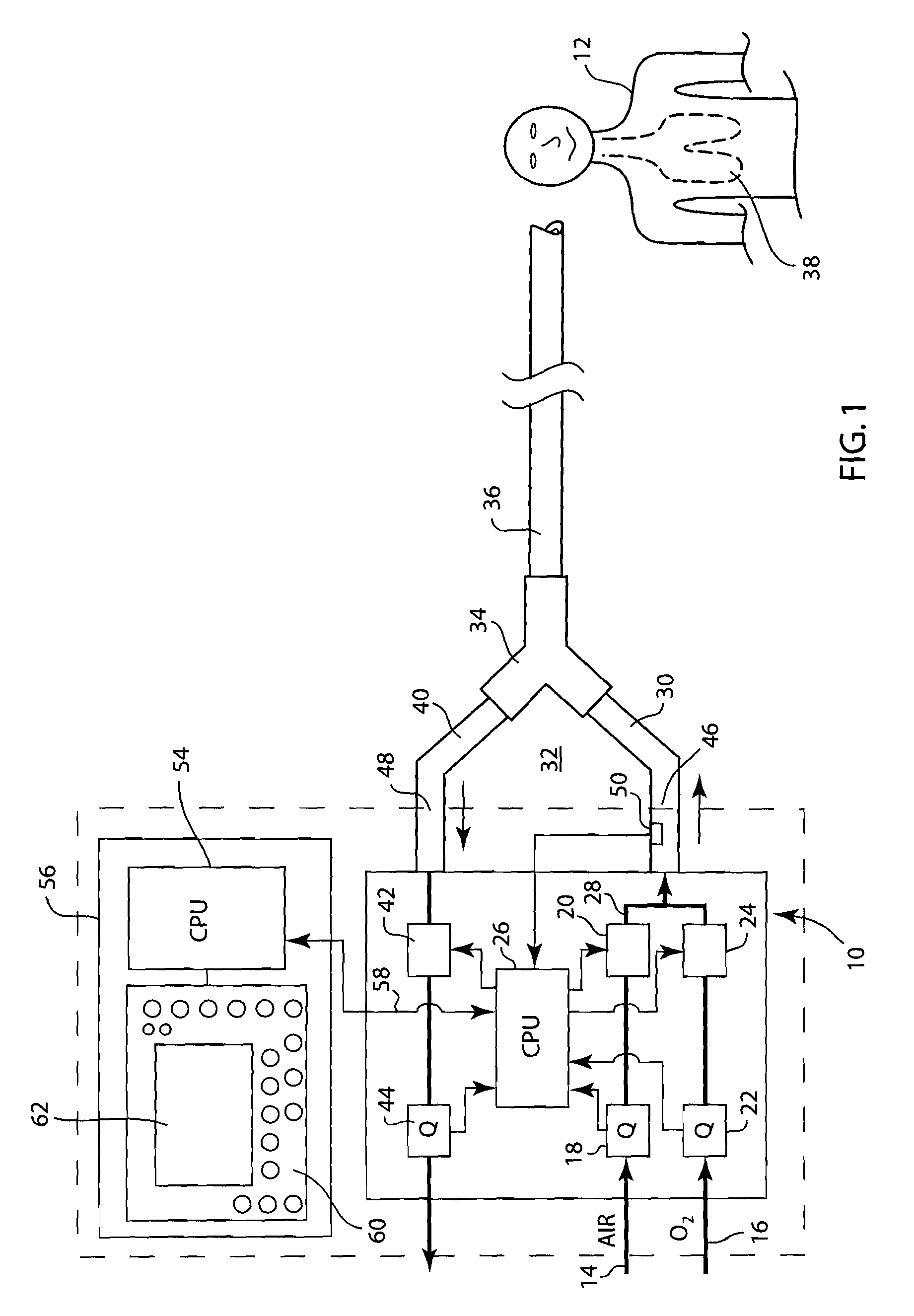
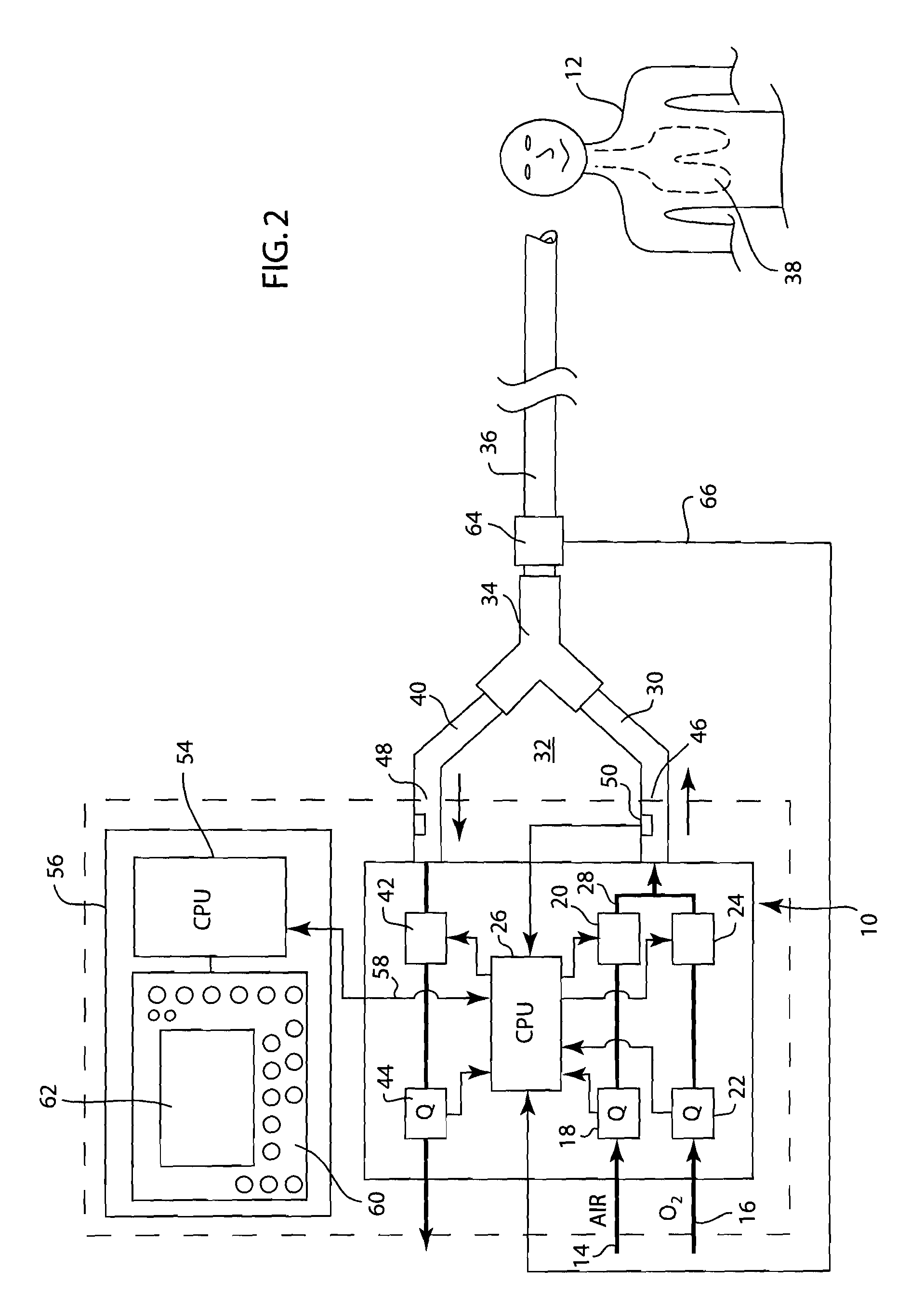
[0013]FIG. 1 shows a mechanical ventilator 10 for providing breathing gas to a patient 12. Ventilator 10 receives air in a conduit 14 from an appropriate source, not shown, such as a cylinder of pressurized air or a hospital air supply manifold. Ventilator 10 also receives pressurized oxygen in conduit 16 from an appropriate source, not shown, such as a cylinder or manifold. The flow of air in ventilator 10 is measured by flow sensor 18 and controlled by valve 20. The flow of oxygen is measured by flow sensor 22 and controlled by valve 24. The operation of valves 20 and 24 is established by a control device such as central processing unit 26 in the ventilator.

[0014]The air and oxygen are mixed in conduit 28 of the ventilator 10 and provided to inspiratory limb 30 of breathing circuit 32. A nebulizer (not shown) can be positioned between the ventilator 10 and the inspiratory limb 30 to introduce a medical drug as desired by the clinician. Inspiratory limb 30 is connected to one arm o...


PUM


Abstract

A method and system for ventilating a patient that compensates for leaks occurring within the patient breathing circuit while limiting the volume of breathing gas delivered to the patient. During the operation of a ventilator to supply breathing gases to a patient, the ventilator monitors for leak volumes occurring during the inspiratory phase and expiratory phase of the breathing cycle. Based upon the leak volumes sensed, the volume of breathing gas delivered by the ventilator is increased such that the tidal volume delivered to the patient is the desired tidal volume set by a clinician. The ventilator operates to generate a leak alarm when the leak volume exceeds an alarm threshold. If the leak alarm is generated, the tidal volume delivered to the patient is limited to the tidal volume being delivered prior to generation of the leak alarm. During compensation of the breathing gases delivered to the patient, the system and method determines whether the compensated tidal volume exceeds a maximum tidal volume threshold and limits the compensated tidal volume to the maximum tidal volume threshold.

Description

BACKGROUND OF THE INVENTION[0001]The present disclosure relates to a method of operating a ventilator. More specifically, the present disclosure relates to a method of operating a ventilator to compensate for leaks within the breathing circuit while limiting the maximum volume of breathing gas that can be delivered to the patient.[0002]Ventilators, such as the Engstrom Carestation available from GE Healthcare, exist that supply a volume of breathing gas to a patient. The ventilator includes a display unit that allows the operator to monitor the delivery of breathing gases to the patient and control the supply of the breathing gases depending upon the response of the patient to the treatment. Typically, the ventilator is connected to a breathing circuit that includes a patient limb that delivers the breathing gases to the patient through typical patient interfaces, such as a breathing mask, endotracheal tube or nasal cannula.[0003]During operation of the ventilator, the ventilator ge...

Claims


Application Information

Patent Timeline
Patent Type & Authority Applications(United States)
IPC IPC(8): A61M16/00A61B5/08
CPCA61M16/0051A61M16/12A61M16/16A61M2016/0039A61M2016/0042A61M2202/0208A61M2205/502A61M16/024
Inventor MCCORMICK, TIMOTHY P.TOBIA, RONALD L.
Owner GENERAL ELECTRIC CO
Why Eureka
Try Eureka