Connection head for an absorber of an anesthetic breathing system
- Summary
- Abstract
- Description
- Claims
- Application Information
AI Technical Summary
Benefits of technology
Problems solved by technology
Method used
Image
Examples
Embodiment Construction
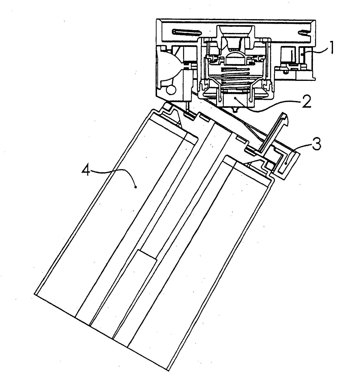
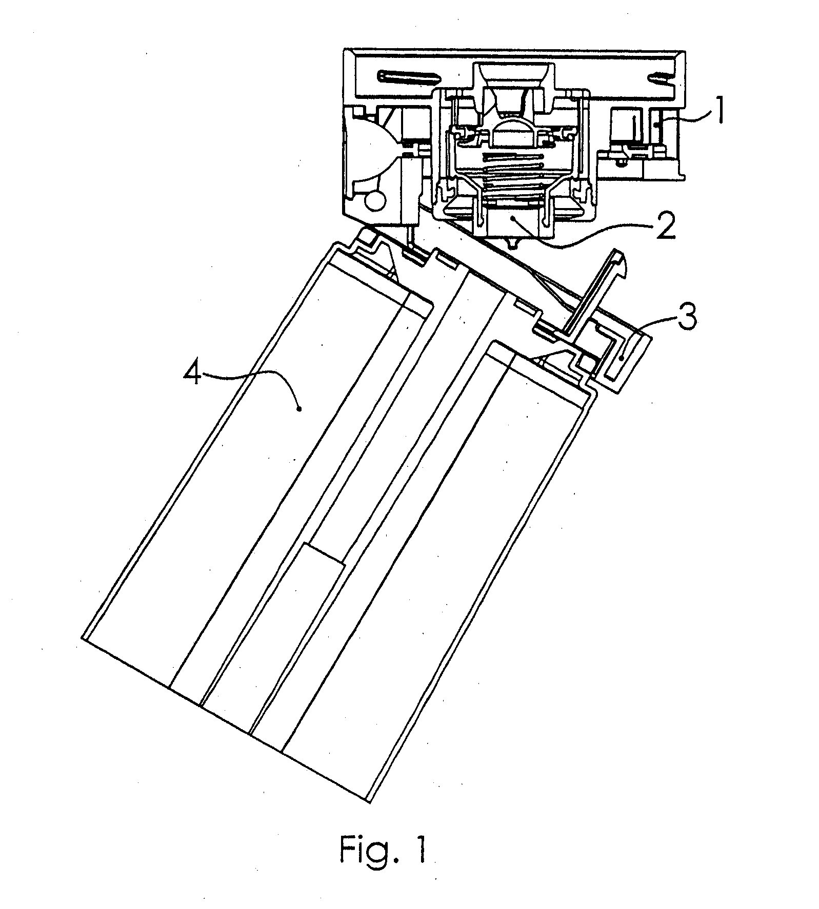
[0019]Referring to the drawings in particular FIG. 1 schematically shows a longitudinal section of a connection head 1 with a valve means 2 and with an absorber 4 accommodated in a pivotable mount 3.
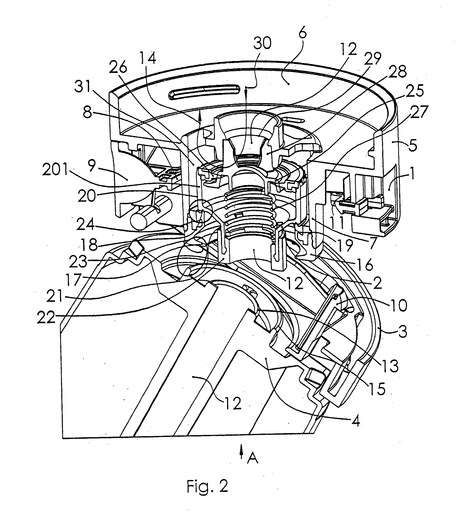
[0020]FIG. 2 schematically illustrates the connection area between the connection head 1 and the absorber 4. The connection head 1 has a housing 5 with a connection piece 6 for connection to an anesthetic breathing system, not shown more specifically in FIG. 2; a guide sleeve 7, which accommodates the valve means, and a ring-shaped locking element 8 within the housing 5 with a release button 9.
[0021]The mount 3, which receives the absorber 4, has a barb 10, which snaps into a wall section 11 of the locking element 8. To connect the absorber 4 to the connection head 1, the absorber 4 is pushed into the mount 3 and pivoted in the direction of the connection head 1. Reference is made in this connection to DE 10 2004 020 133 B3, which is part of this specification (corresponding to U.S. appl...
PUM
 Abstract
Description
Claims
Application Information
 - R&D
- Intellectual Property
- Life Sciences
- Materials
- Tech Scout
- Unparalleled Data Quality
- Higher Quality Content
- 60% Fewer Hallucinations
Browse by: Latest US Patents, China's latest patents, Technical Efficacy Thesaurus, Application Domain, Technology Topic, Popular Technical Reports.
© 2025 PatSnap. All rights reserved.Legal|Privacy policy|Modern Slavery Act Transparency Statement|Sitemap|About US| Contact US: help@patsnap.com


