Method for configuring virtual network and network system

a network and virtual network technology, applied in the field of virtual network configuration, can solve the problems of unable to distribute data across a plurality of nics for large-bandwidth communication between two computers, places limitations on network configuration, and troublesome operation of pm library without modifying an existing application program

Inactive Publication Date: 2008-12-04
HITACHI LTD
View PDF2 Cites 137 Cited by
  • Summary
  • Abstract
  • Description
  • Claims
  • Application Information

AI Technical Summary

Benefits of technology

[0016]According to one aspect of the invention, a method for configuring a virtual network is provided, which is described below: in a network system including a first computer and a second computer, each having one or more physical network interfaces, and a network connecting the first computer and the second computer, wherein the first computer and the second computer can communicate with each other over the physical network interfaces, a method for configuring a virtual network between the first computer and the second computer, the method including: at the first computer, configuring a virtual network interface to be used for data transmission and reception by an application running on the first computer; setting up a virtual channel between the configured virtual network interface and a virtual network interface configured on the second computer and storing a correspondence between the set up virtual channel and the virtual network interfaces as virtual channel information; setting up a physical channel between a physical network interface on the first computer and a physical network interface on the second computer and storing a correspondence between the set up physical channel and the physical network interfaces as physical channel information; measuring traffic of data transmitted and received over the virtual channel and storing the traffic measurement results in the virtual channel information; when detecting a data transmission instruction to the virtual network interface, setting a correspondence between the virtual channel set up on the virtual network interfaces and one or more the physical channels, based on predetermined priority of the virtual channel and statistical information as the traffic measurement results stored, and storing the correspondence between the virtual channel and the one or more physical channels in the physical channel information; and transmitting the correspondence between the virtual channel and the one or more physical channels to the second computer having the virtual network interface to which the data transmission instruction is addressed; at the second computer, when receiving the correspondence between the virtual channel and the one or more physical channels, storing the received correspondence between the virtual channel and the one or more physical channels in the physical channel information, wherein the first computer transmits data in accordance with the data transmission instruction, using one or more the physical channels associated with the virtual channel, based on the correspondence stored.
[0017]As priority indicators, priority control information is used, such as a predetermined number of parallel connections and weighting value per virtual network (channel). As statistical information, virtual channel usage, or use frequency is used.

Problems solved by technology

Thus, since one same NIC always receives packets between two computers, it is impossible to distribute data across a plurality of NICs for large-bandwidth communication between two computers.
This places limitations on network configurations.
This means that running the PM library without modifying an existing application program would be a trouble.

Method used


Image

  • Method for configuring virtual network and network system
  • Method for configuring virtual network and network system
  • Method for configuring virtual network and network system

Examples


Embodiment Construction

[0029]Embodiments of the present invention will now be described with reference to the drawings.

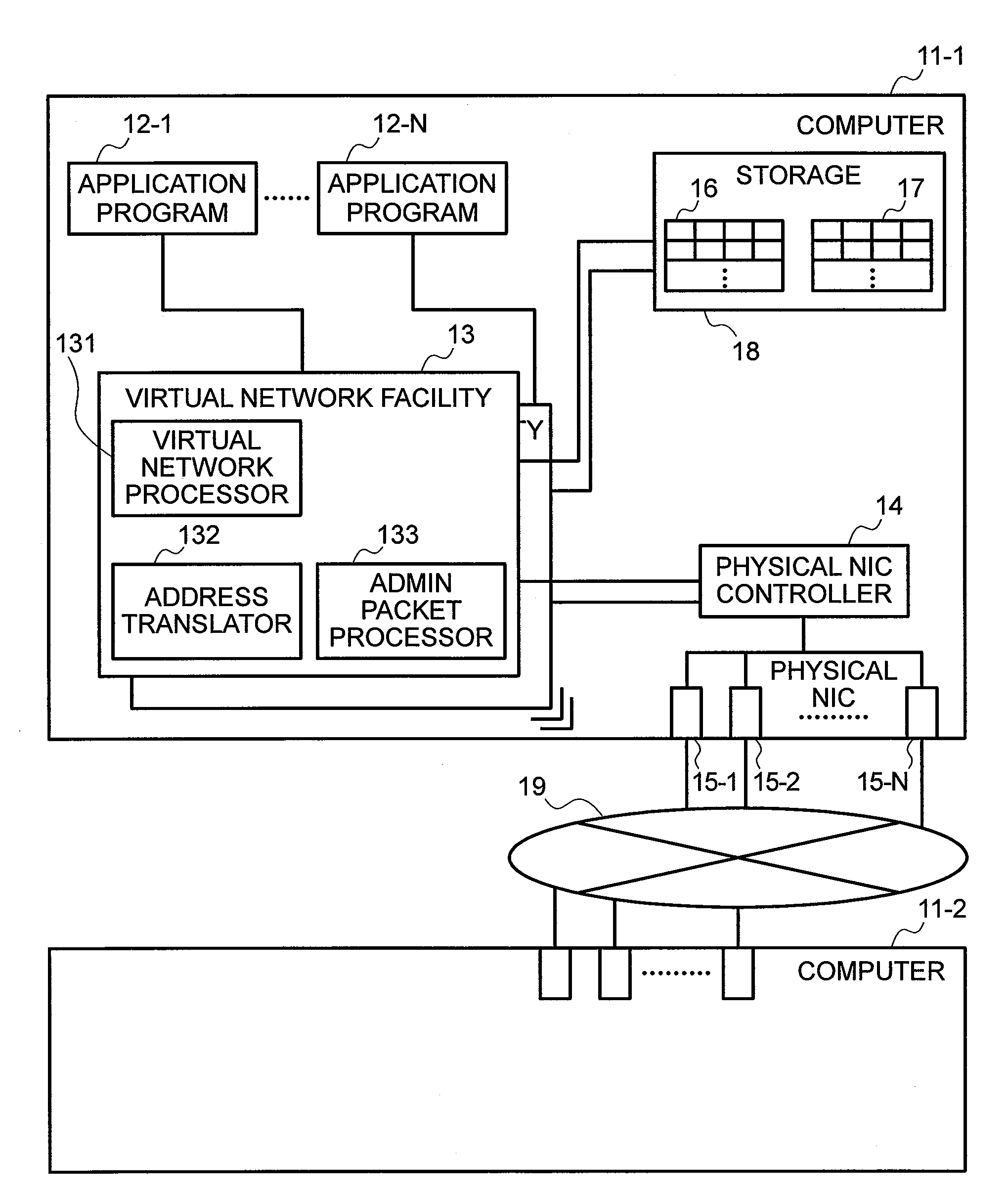
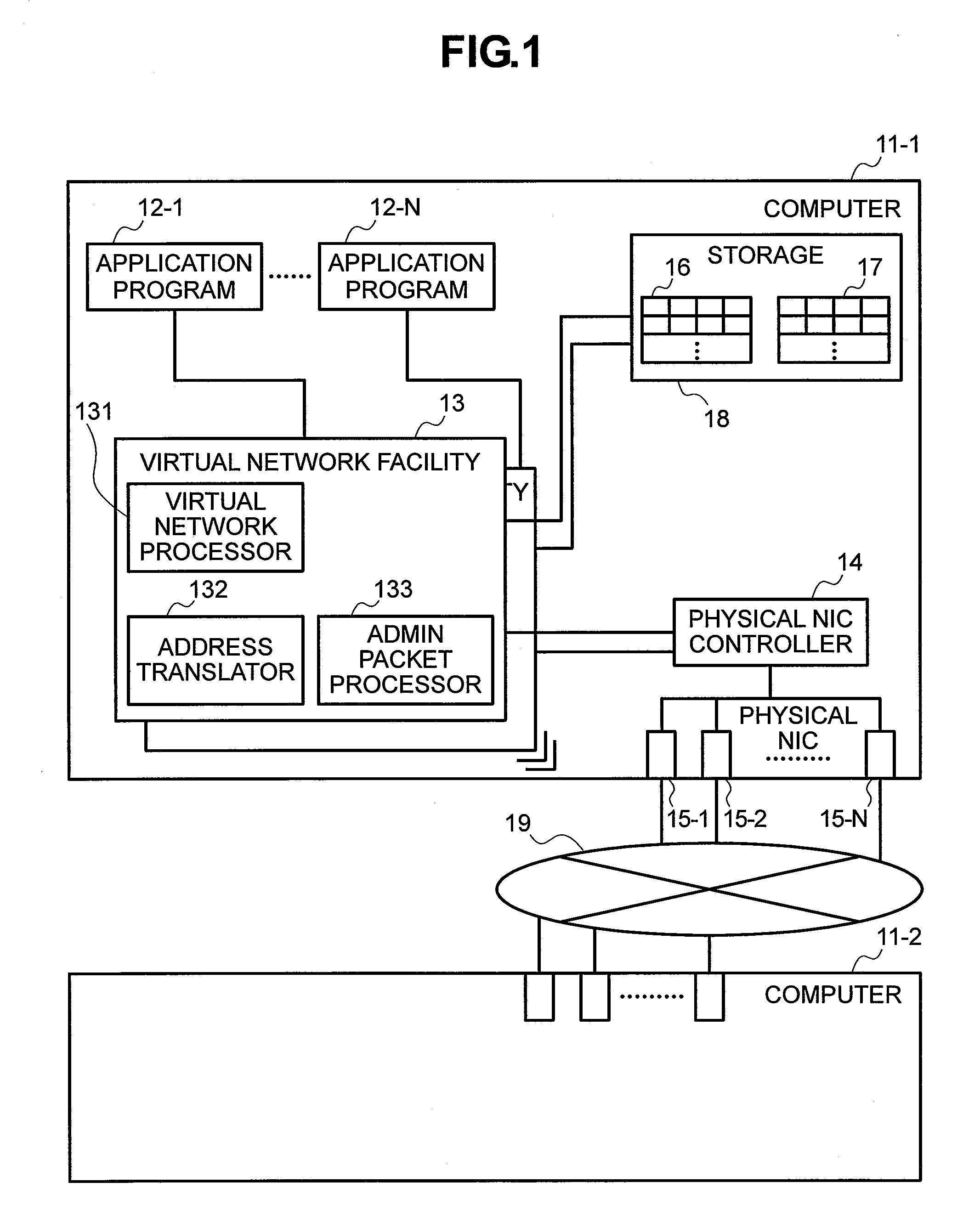
[0030]FIG. 1 is a block diagram showing a framework of a virtual network system according to an embodiment of the invention.

[0031]The virtual network system shown in FIG. 1 is comprised of one or more computers 11 (11-1, 11-2) and a network 19 connecting the computers. The computers 11-1, 11-2 are connected via the network 19.

[0032]Each computer 11 has N pieces of physical network interface cards (physical NICs) 15 (15-1, 15-2, 15-N).

[0033]A computer 11 includes one or more application programs 12 (12-1, 12-2, . . . , 12-N), one or more virtual network facilities 13, a physical NIC controller 14, and a storage 18. In the storage 18, a virtual channel table 16 and a physical channel table 17 are stored.

[0034]A virtual network facility 13 includes a virtual NIC processor 131, an address translator 132, and an administrative packet processor 133. The virtual network facility 13 refers to and...


PUM


Abstract

A first computer stores a correspondence between a virtual channel and a physical channel(s) in physical channel information and transmits the correspondence between the virtual channel and the physical channel(s) to a second computer having a virtual network interface to which a data transmission instruction is addressed. Upon receiving the correspondence between the virtual channel and the physical channel(s), the second computer stores the received correspondence in the physical channel information. The first computer transmits data in accordance with the data transmission instruction, using one or more physical channels associated with the virtual channel, based on the correspondence stored.

Description

[0001]The present application claims priority from Japanese application serial no. JP 2007-137754, filed on May 24, 2007, the content of which is hereby incorporated by reference into this application.BACKGROUND OF THE INVENTION[0002]The present invention relates a method for configuring a virtual network, whereby a virtual network is configured between computers and managed, and a network system.[0003]In computer systems, recently, high-speed network connection becomes an important challenge. In particular, data backup processing between servers requires large-bandwidth data transfer between servers.[0004]As a bandwidth enhancement technique for computer networks, there is a heretofore known technique in which a plurality of network interface cards (hereinafter referred to as NICs) are aggregated into one interface that is virtually assumed as a single interface.[0005]For example, a bonding technique is used in a Linux operating system. Bonding enables an increase in the bandwidth ...

Claims


Application Information

Patent Timeline
Patent Type & Authority Applications(United States)
IPC IPC(8): H04L12/28H04L12/70H04L12/801H04L12/911
CPCH04L12/2602H04L12/4641H04L41/08H04L43/00H04L41/0895
Inventor TAKASHIGE, SOUICHISHIGA, YOKO
Owner HITACHI LTD
Why Eureka
Try Eureka