Target positioner

a positioner and target technology, applied in the field of target positioners, can solve the problems of undesirable displacement or misalignment of the radiation beam, light misalignment between the three, and prior art methods, therefore, suffer from imprecise positional relationships between the tables

Inactive Publication Date: 2008-12-04
EIN GAL MOSHE
View PDF40 Cites 43 Cited by
  • Summary
  • Abstract
  • Description
  • Claims
  • Application Information

AI Technical Summary

Problems solved by technology

Rather, in the real world, there is a slight misalignment between the three, among other things due to the size and weight of the sagging rotating gantry and turntable.
Consequently, an undesirable displacement or misalignment of the radiation beam occurs relative to the turntable.
Prior art methods, therefore, suffer from imprecise positional relationships between the table and the source compounded by uncontrolled target motion relative to the table.

Method used


Image

  • Target positioner
  • Target positioner
  • Target positioner

Examples


Embodiment Construction

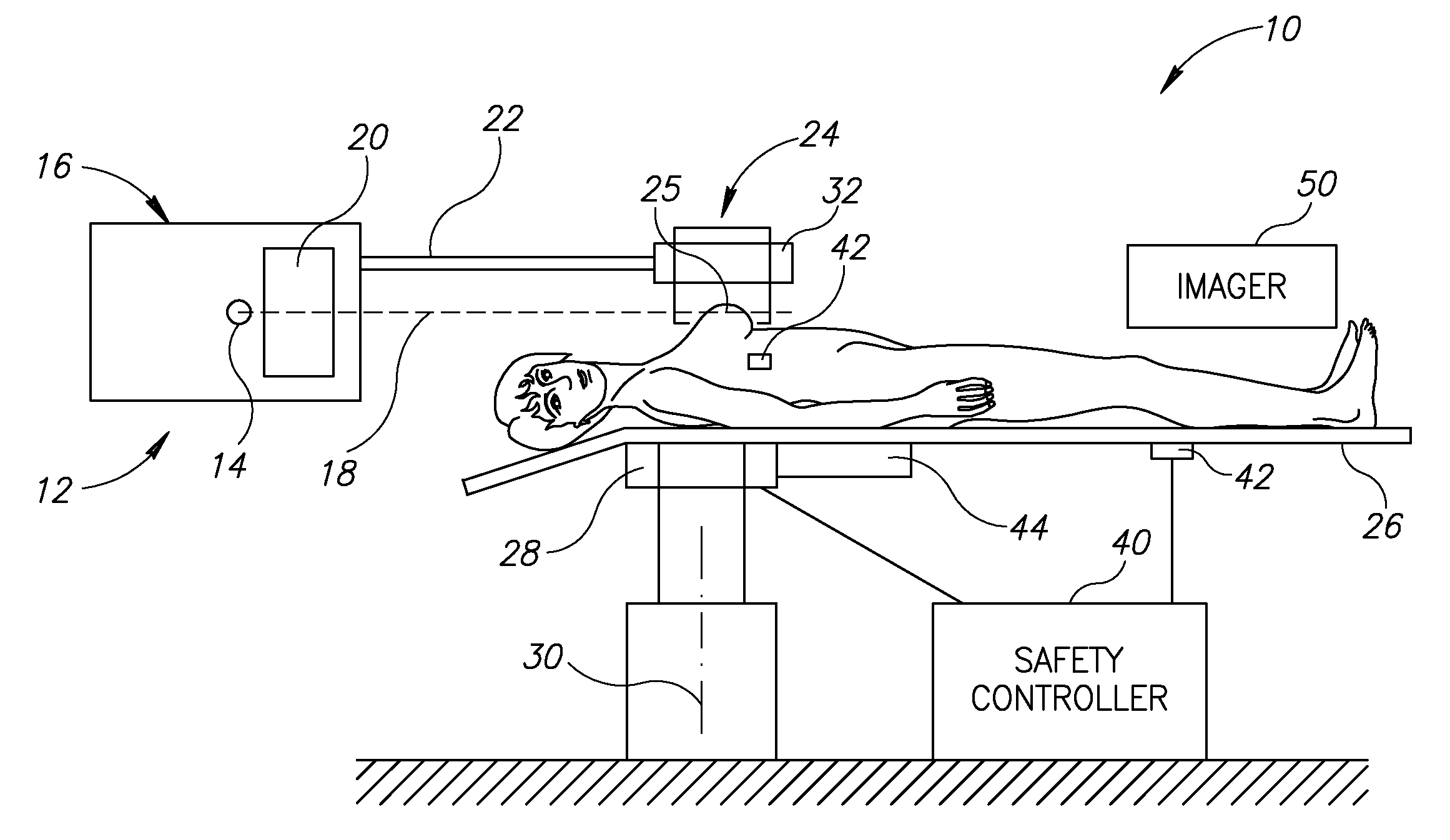
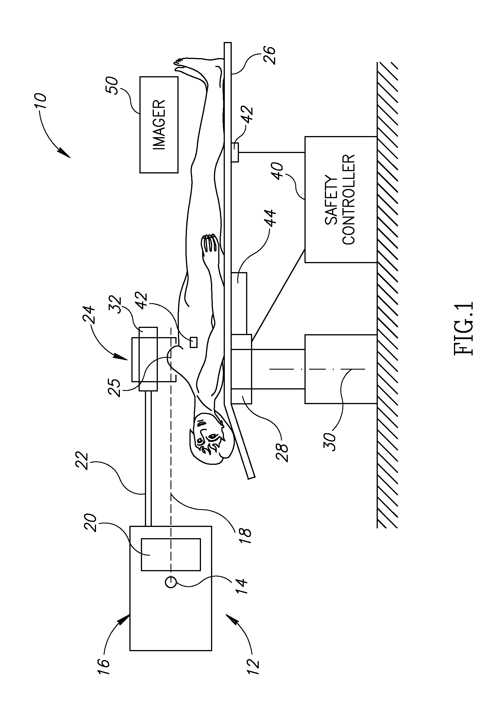
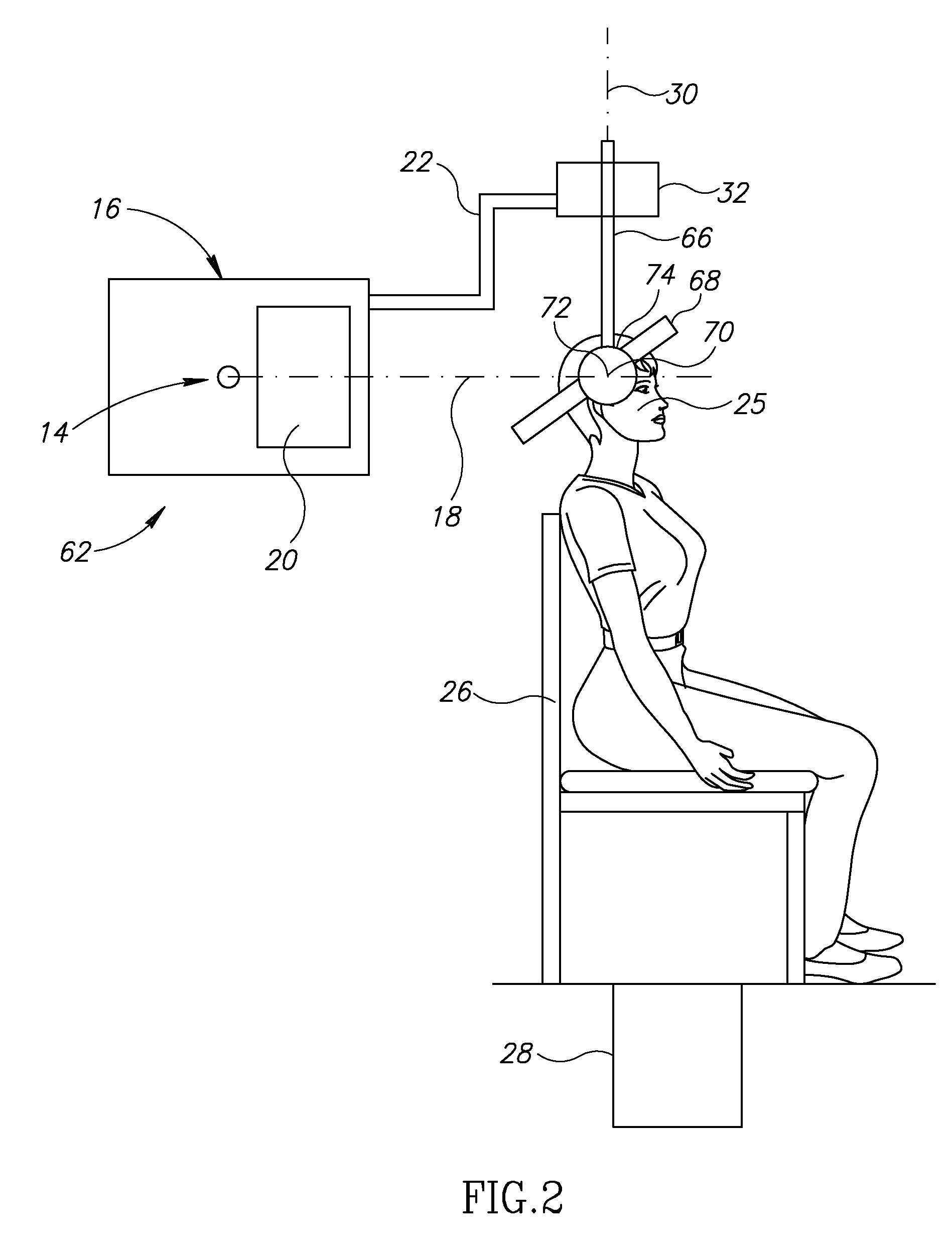
[0012]Reference is now made to FIG. 1, which illustrates a target positioner 10 for use with a radiation system 12, constructed and operative in accordance with an embodiment of the present invention.

[0013]The radiation system 12 includes a radiation source 14 disposed in a stationary source housing 16. Radiation source 14 may be any source suitable that emits a radiation beam 18 for performing irradiation, such as but not limited to, X-ray beams (e.g., at MV energy spectrum or other levels of energy), beta ray beams, positron beams, proton beams, antiproton beams, neutron beams, heavy ion beams, e.g., alpha ray beams, carbon ion beams, etc. Radiation beam 18 may be collimated by a collimator 20, such as but not limited to, a multiple layer multileaf collimator, such as that described in U.S. Pat. Nos. 6,266,393 and 6,526,123 to Ein-Gal, the disclosures of which are incorporated herein by reference.

[0014]Target positioner 10 achieves beam / target positioning by means of a source arm ...


PUM


Abstract

A target positioner including a radiation source disposed in a source housing, the radiation source adapted to emit a radiation beam, a target holder adapted to be attached to and generally immobilize a target organ, the target holder being rotatingly attached to a bearing assembly, a patient support table for supporting a patient thereon, a rotator for turning the patient support table about a rotation axis, and a source arm fixedly attached at one portion thereof to the source housing and at another portion thereof to the bearing assembly, such that when the target holder is attached to a target organ and the rotator turns the patient support table about the rotation axis, the target holder constrains the target organ from translating with respect to the radiation source and the source housing, and wherein the target holder permits the target organ to rotate by means of the bearing assembly relative to the source housing while experiencing slight translations with respect to the patient support table, so that the radiation beam emanating from the radiation source impinges upon the target organ at a plurality of angles irrespective of the misalignments between the radiation beam and the patient support table and between the patient support table and the target organ.

Description

FIELD OF THE INVENTION[0001]The present invention relates generally to irradiation systems for delivering radiation beams to a target, and more particularly to a target positioner that constrains a target organ to be precisely positioned with respect to a radiation source.BACKGROUND OF THE INVENTION[0002]Irradiating a target, such as in radiation treatment, requires a multiplicity of orientations between a target to be irradiated and a radiation beam. Typically, a radiation source is mounted on a gantry that rotates about a horizontal gantry axis. The radiation beam intersects, and is generally perpendicular to, the gantry axis. A patient is supported by a turntable that rotates the target about a vertical target axis, which theoretically intersects the gantry axis. Linear accelerators and cobalt therapy devices incorporate such gantry and turntable rotations to accomplish multi-orientation irradiation.[0003]Since the beam is positioned by the gantry while the target is independentl...

Claims


Application Information

Patent Timeline
Patent Type & Authority Applications(United States)
IPC IPC(8): A61B6/00
CPCA61B6/0414A61B6/0421A61B6/102A61B6/502A61N5/1049A61N2005/1097
Inventor EIN-GAL, MOSHE
Owner EIN GAL MOSHE
Why Eureka
Try Eureka