Image Forming Device and Semiconductor Device

a technology of image forming device and semiconductor, which is applied in the direction of instruments, electrographic process devices, optics, etc., can solve the problems of cost increase and limited life of the devi

Active Publication Date: 2008-12-04
RICOH KK
View PDF4 Cites 23 Cited by
  • Summary
  • Abstract
  • Description
  • Claims
  • Application Information

AI Technical Summary

Benefits of technology

[0016]In one aspect of the invention, the present disclosure provides an improved image forming device in which the above-described problems are eliminated.
[0017]In one aspect of the invention, the present disclosure provides an image forming device which carries out an appropriate speed control to eliminate speed fluctuations of the peripheral speed of a secondary transfer roller and the surface speed of an intermediate transfer belt without increasing the number of component parts and the cost.
[0028]The above-mentioned image forming device may be arranged so that the target value selecting unit is configured to select a target value which minimizes a difference between the peripheral speed of the second rotary member and the surface speed of the intermediate transfer belt.
[0032]It is possible that the image forming device of the invention carries out an appropriate speed control to eliminate speed fluctuations of the peripheral speed of the secondary transfer roller and the surface speed of the intermediate transfer belt without increasing the number of component parts and the cost.

Problems solved by technology

The torque limiter in the above-mentioned image forming device as disclosed in Japanese Laid-Open Patent Application No. 11-052757 is a mechanical part, and the life thereof is restricted.
Installing the torque limiter in the image forming device also causes the cost to increase.

Method used


Image

  • Image Forming Device and Semiconductor Device
  • Image Forming Device and Semiconductor Device
  • Image Forming Device and Semiconductor Device

Examples


second embodiment

[0165]Next, the invention will be explained.

[0166]In the second embodiment of the invention, the composition of the output monitoring unit 500 differs from that in the first embodiment. Other components of the second embodiment are the same as those of the first embodiment. A description will be given of only the difference in the output monitoring unit 500 between the second embodiment and the first embodiment. In the second embodiment, the elements which are the same as corresponding elements in the first embodiment are designated by the same reference numerals, and a description thereof will be omitted.

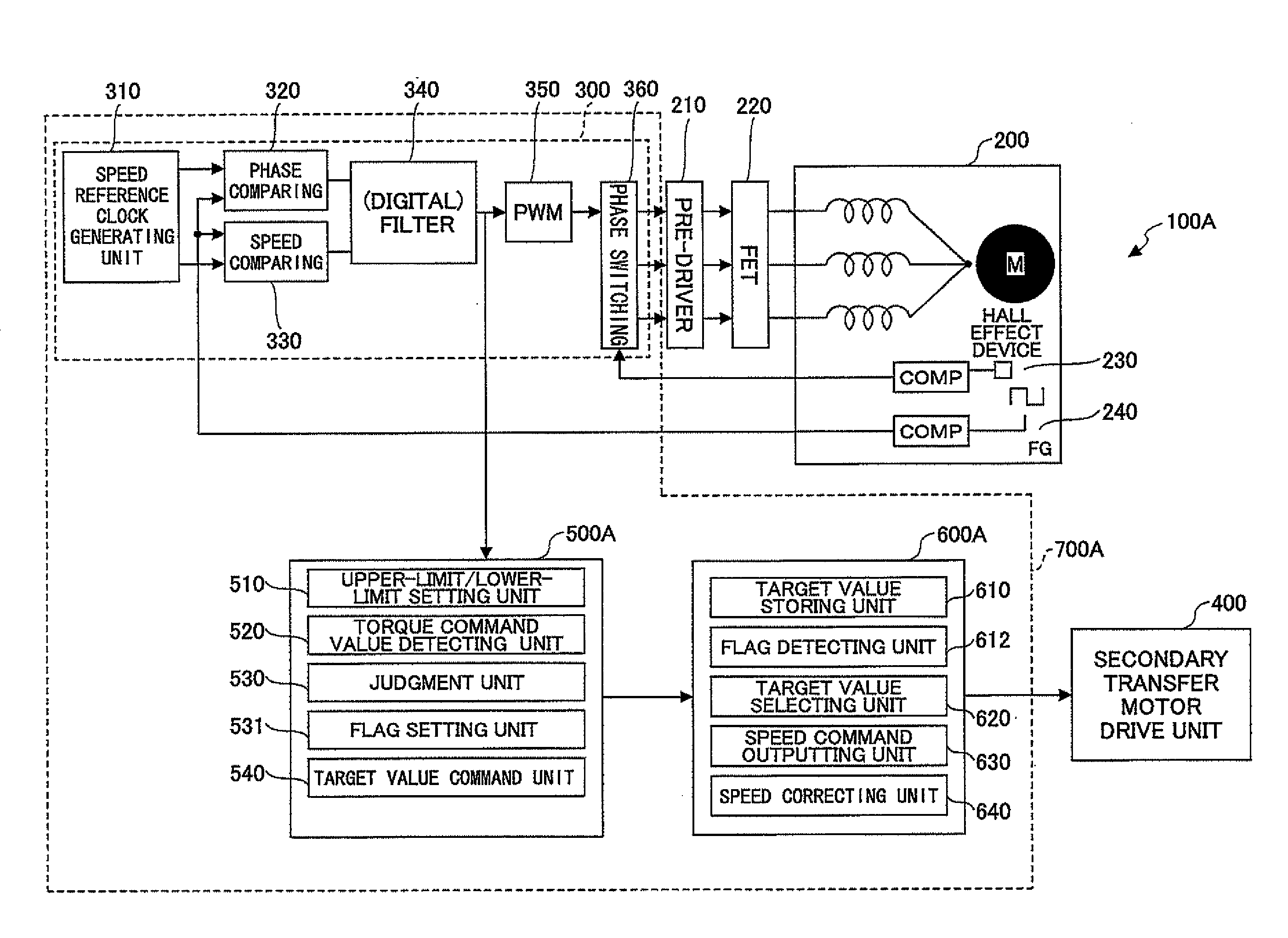
[0167]The image forming device 100B of this embodiment is arranged to detect that the intermediate transfer drive motor 200 is held in an uncontrollable state, and control the rotational speed of the secondary transfer roller 71 on such an occasion. In the image forming device 100B, when the PWM value (torque command value) decreases from the first lower limit to the second lower l...

first embodiment

[0188]The output monitoring unit 5003 of this embodiment detects periodically a PWM value output from the digital filter to the PWM unit 350 of the intermediate transfer drive motor driving unit 300. The initial operation of the image forming device 100B is the same as that in the first embodiment, and a description thereof will be omitted.

[0189]In step S1301, the output monitoring unit 500B determines whether the detection mode is set up. When the detection mode is set up, the control progresses to step S1302. In step S1302, the output monitoring unit 500B detects a PWM value by using the torque command value detecting unit 520.

[0190]Progressing to step S1303, the judgment unit 530A determines whether the detected PWM value is smaller than the first lower limit P.

[0191]When the PWM value is smaller than the first minimum P, the control progresses to step S1304. In step S1304, the judgment unit 530A determines whether the detected PWM value is smaller than the second lower limit Q.

[...

third embodiment

[0200]Next, the image forming device of the invention will be explained.

[0201]The image forming device of the third embodiment is a modification of the second embodiment described above. The third embodiment differs from the second embodiment in that an output detecting unit 500C detects a PWM value equivalent to the first lower limit P as in the second embodiment. Only the differences of the third embodiment from the second embodiment will be explained. The elements in the third embodiment which are the same as corresponding elements in the second embodiment are designated by the same reference numerals, and a description thereof will be omitted.

[0202]FIG. 17 shows the composition of an image forming device 100C of the third embodiment of the invention.

[0203]The output monitoring unit 50C in the image forming device 100C of this embodiment includes an upper-limit / lower-limit setting unit 510B, a torque command value detecting unit 520, a judgment unit 530B, a flag setting unit 531,...


PUM


Abstract

In an image forming device including a first rotary member arranged to drive an intermediate transfer belt, a first motor arranged to rotate the first rotary member, and a second rotary member arranged to transfer a toner image formed on the intermediate transfer belt to a recording sheet, a torque command value detecting unit detects a torque command value to the first motor. A setting unit sets up a lower limit of the torque command value. A judgment unit determines whether a detected torque command value exceeds the lower limit. A control unit controls driving of the second rotary member when the detected torque command value exceeds the lower limits so that a difference between a surface speed of the intermediate transfer belt and a peripheral speed of the second rotary member falls within a predetermined range.

Description

BACKGROUND OF THE INVENTION[0001]1. Field of the Invention[0002]This invention relates to an image forming device which includes an intermediate transfer drive motor which rotates an intermediate transfer belt, and a secondary transfer motor which rotates a secondary transfer roller, and relates to a semiconductor device for use in an image forming device.[0003]2. Description of the Related Art[0004]In an image forming device, when a toner image, primarily transferred from a photoconductor drum to an intermediate transfer belt, is secondarily transferred to a recording sheet, the toner image on the intermediate transfer belt is transferred to the recording sheet by nipping the recording sheet between the intermediate transfer belt and a secondary transfer roller which are pressed against each other.[0005]FIG. 1 shows a secondary transfer roller and an intermediate transfer belt in an image forming device. The image forming device 10 shown in FIG. 1 includes a secondary transfer roll...

Claims


Application Information

Patent Timeline
Patent Type & Authority Applications(United States)
IPC IPC(8): G03G15/01
CPCG03G15/167G03G2215/0129
Inventor KOIKE, TAKAHISA
Owner RICOH KK
Why Eureka
Try Eureka