
Handicapped accessible exercise machine

Active Publication Date: 2008-12-04
INCLUDEFITNESS
View PDF30 Cites 92 Cited by
  • Summary
  • Abstract
  • Description
  • Claims
  • Application Information

AI Technical Summary

Benefits of technology

[0007]The present invention relates to a weight lifting machine that incorporates several features for allowing both able-bodied users and users with limited mobility and / or dexterity to easily and effectively perform a wide variety of weightlifting exercises.
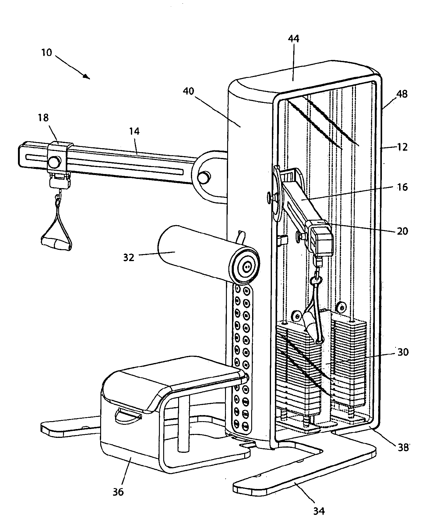
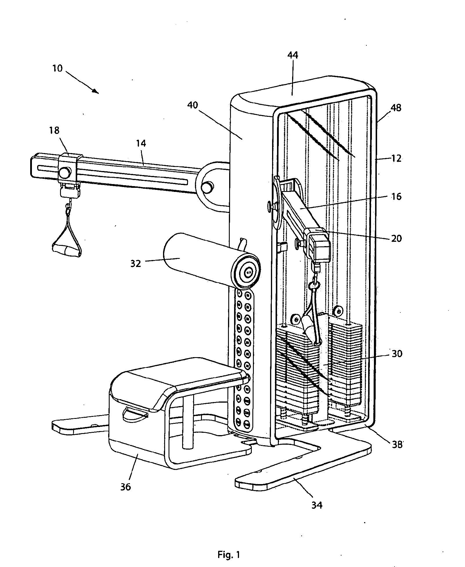
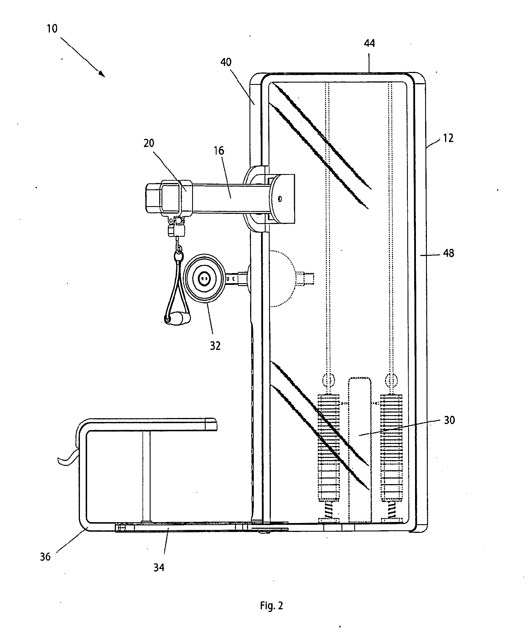
[0008]The apparatus of the present invention preferably includes a central housing with two weight stacks enclosed therein. Two extension arms are pivotably mounted to opposite sides of the housing. Each arm can be releasably locked in a pivoted position relative to the housing. Each arm has a cable guide that can be slidably moved and releasably locked along the length of its respective arm. Cables are linked to each weight stack and extend to the cable guides through a series of pulleys in the manner of a conventional weightlifting machine. A user may thus connect a user interface, such as a handlebar, rope, or strap to the cables for performing various exercises. It is preferred that the cables terminate in J-hooks so that a user with limited manual dexterity can easily connect and disconnect various user interfaces.
[0010]Button-operated push-locks are preferably mounted to the apparatus for allowing the adjusted positions of the extension arms and the cable guides to be releasably secured. Each of the push-locks operates in the manner of a conventional click-pen and allows a user to lock and unlock the positions of the arms and the guides by successively pressing a button. The push-locks are incorporated as an alternative to conventional, spring-loaded locking pins for allowing users with diminished finger dexterity to easily adjust and secure the configuration of the apparatus.
[0011]A resistance assembly is preferably located within the central housing and includes a solenoid tower having two solenoid driven pins mounted to vertically movable tracks. The solenoid tower is operatively connected to a user interface located on the front of the housing. The user interface is provided with a plurality of buttons that each correspond to weight increments of the weight stacks in the central housing. When a user presses a button that corresponds to a desired weight increment, the solenoid tower shifts locking pins into engagement with the appropriate weights in the weight stacks to offer the desired amount of resistance. The solenoid tower and the user interface are provided as an alternative to conventional, spring-loaded locking pins for allowing users with diminished finger dexterity to easily adjust the amount of resistance provided by the apparatus.
[0012]An adjustable support pad preferably extends from the front of the central housing for restricting the movement of a user relative to the central housing and allowing a user to isolate specific muscle groups while performing a workout. The pad can preferably be extended, retracted, and vertically pivoted relative to the housing for accommodating different users and different exercises. Button-operated solenoids are preferably provided for allowing a user to easily lock the pad in various positions along its range of motion.

Problems solved by technology

These features make it difficult, and sometimes impossible, for handicapped users having limited mobility and dexterity to effectively use the machines.
For example, a wheelchair-bound paraplegic user may not be able to lift himself onto a bench or move into a cramped space behind the chest pad of a traditional weight machine.
Similarly, a user having diminished finger dexterity may have a great deal of difficulty operating conventional spring-loaded locking pins of the type commonly used in weight machines for securing the positions of the machine's adjustable components.
Due to the spatial requirements of a wheelchair and the limited mobility of a wheelchair's occupant, most weight training machines that are designed for wheelchair-bound users feature highly specialized structures and configurations.
The result of this high degree of specialization is that conventional “wheelchair friendly” machines have traditionally exhibited a lack of versatility.
Most of these machines are very large and very expensive, but are only capable of facilitating a single type of exercise.
Moreover, most weight machines that are designed for accommodating wheelchairs are poorly suited for users who do not use wheelchairs.
Therefore, in order for a training facility to provide a complete array of wheelchair friendly equipment, the facility must spend a great deal of money and allocate a great deal of floor space to purchase and accommodate a plurality of machines that are largely unusable by the non-wheelchair-bound majority of its clientele.
Such an investment is not economically practical for most facilities, thus leaving wheelchair-bound individuals with limited and ill-suited options for weight training.

Method used


Image

  • Handicapped accessible exercise machine
  • Handicapped accessible exercise machine
  • Handicapped accessible exercise machine

Examples


Embodiment Construction

[0057]As shown in FIGS. 1-4, the exercise machine 10 is generally provided with a central housing 12, pivoting extension arms 14 and 16, sliding cable guides 18 and 20, independent cable systems 22 and 24, user interfaces 26 and 28, a resistance assembly 30, an adjustable support pad 32, a wheelchair stabilization member 34, and a sliding bench 36. For the sake of convenience and clarity, terms such as “front,”“rear,”“top,”“bottom,”“up,”“down,”“inwardly,”“outwardly,”“lateral,” and “longitudinal” will be used herein to describe the relative placement and orientation of various components of the invention, all with respect to the geometry and orientation of the machine 10 as it appears in FIG. 1. Said terminology will include the words specifically mentioned, derivatives thereof, and words of similar import.

[0058]The central housing 12 is a vertically elongated, generally rectangular enclosure having a base 38, a front wall 40, a rear wall 42, and a top 44 that are preferably formed o...


PUM


Abstract

A handicapped accessible exercise apparatus having a central housing with two pivoting extension arms. Cables extend from weight stacks within the housing to movable cable guides on the arms for engagement by a user. By adjusting the positions of the arms and the cable guides, the apparatus can be configured to facilitate various exercises and to accommodate users of various sizes. The apparatus is provided with button-operated locks for allowing users with limited manual dexterity to easily lock and unlock the positions of the extension arms and the cable guides.

Description

BACKGROUND OF THE INVENTION[0001]1. Field of the Invention[0002]This invention relates generally to exercise equipment and more particularly to a handicapped accessible exercise machine that incorporates a number of features to simplify operation for users having limited mobility and / or dexterity.[0003]2. Description of the Related Art[0004]The vast majority of weight training machines that are currently available on the market are designed to accommodate users who possess a full or nearly full range of physical mobility and dexterity. Such machines often incorporate features that require a user to perform intricate manual adjustments to attach and adjust various components, or that require users to position and orient their bodies in tight spaces to accommodate the machines' seating and muscle isolation structures (i.e., benches, backrests, support pads, etc). These features make it difficult, and sometimes impossible, for handicapped users having limited mobility and dexterity to ...

Claims


Application Information

Patent Timeline
IPC IPC(8): A63B21/062
CPCA63B21/062A63B21/156A63B2021/0623A63B2071/0018A63B2225/09A63B21/0628A63B21/063
Inventor EDER, JAMES RYAN
Owner INCLUDEFITNESS
Learn More