Adjustable spinal system

a spinal system and adjustment technology, applied in the field of spinal implants, can solve the problems of inability to use a system, multiple consecutive joints that require stabilization, and inability to adjust the vertebrae to line up the pedicle screws, etc., and achieve the effect of convenient force application

Inactive Publication Date: 2008-12-04
LIEPONIS JONAS V
View PDF1 Cites 22 Cited by
  • Summary
  • Abstract
  • Description
  • Claims
  • Application Information

AI Technical Summary

Benefits of technology

[0017]It is further contemplated that the individual plates may be configured with a cross-bar positioned in the slot forming essentially two consecutive elongated slots in each plate. This provides the advantage of allowing the physician to apply either compression or distraction to the pedicle screws more easily during less invasive surgical procedures. Further, each plate may be provided with a notch at each end, which will also allow for easier application of force on the pedicle screws by the physician.

Problems solved by technology

However, a problem arises when multiple consecutive joints require stabilization.
The problem arises due to the various anatomical differences that occur in the spine from patient to patient.
The latter approach is disfavored as adjustment of vertebrae to line up the pedicle screws is highly undesirable and may not be possible, as is insertion of the pedicle screws in less optimal locations to achieve a relatively straight line.
However, where removal of the disc is not required or advisable, this type of system is not usable.

Method used


Image

  • Adjustable spinal system
  • Adjustable spinal system
  • Adjustable spinal system

Examples


Embodiment Construction

[0031]Referring now to the drawings, wherein like reference numerals designate corresponding structure throughout the views.

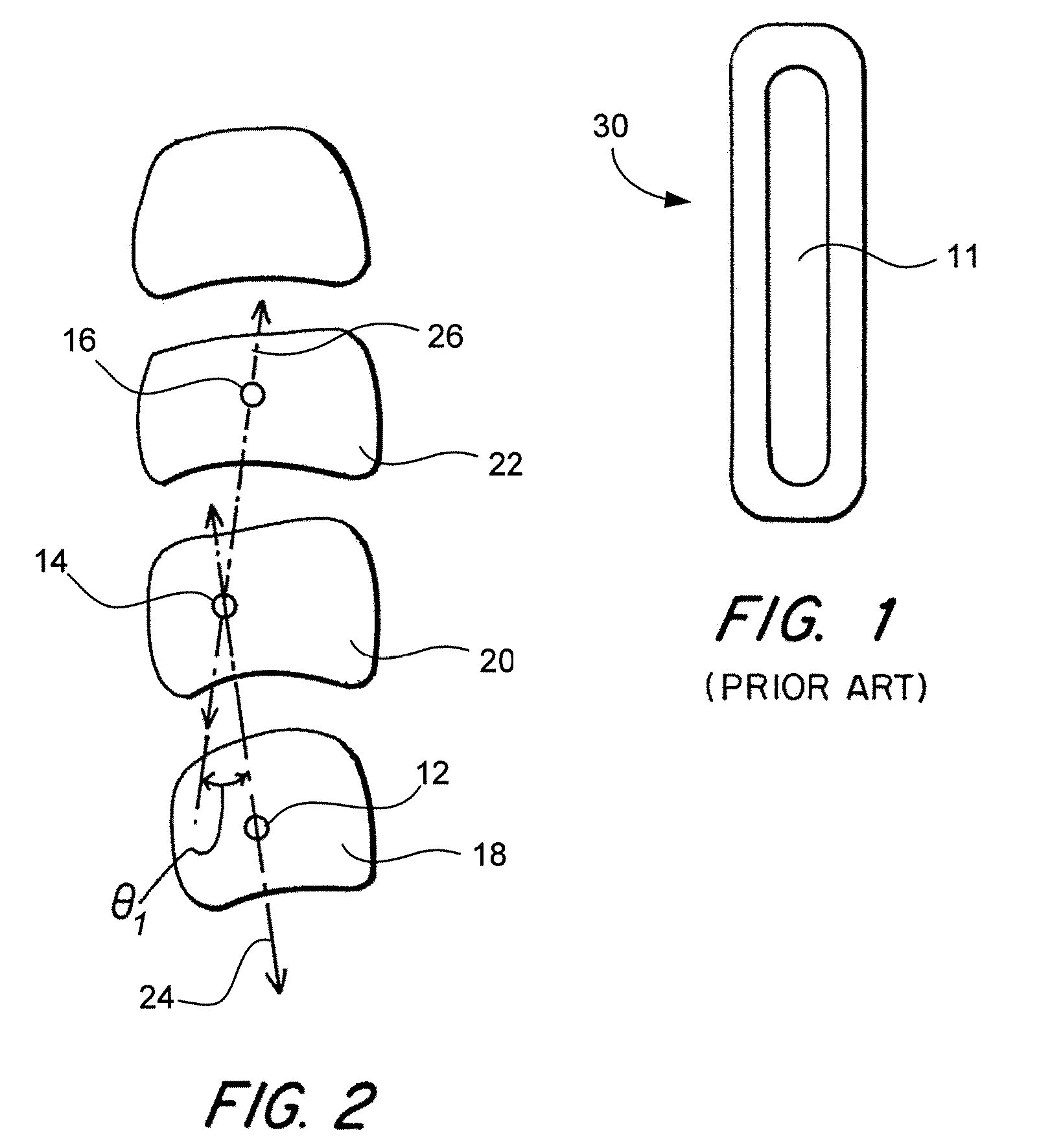
[0032]FIG. 1 illustrates a plate 10 according to the prior art. The plate 10 is generally provided as an elongated device having an elongated slot 11 provided therein for fitting over screws variously positioned in vertebrae.

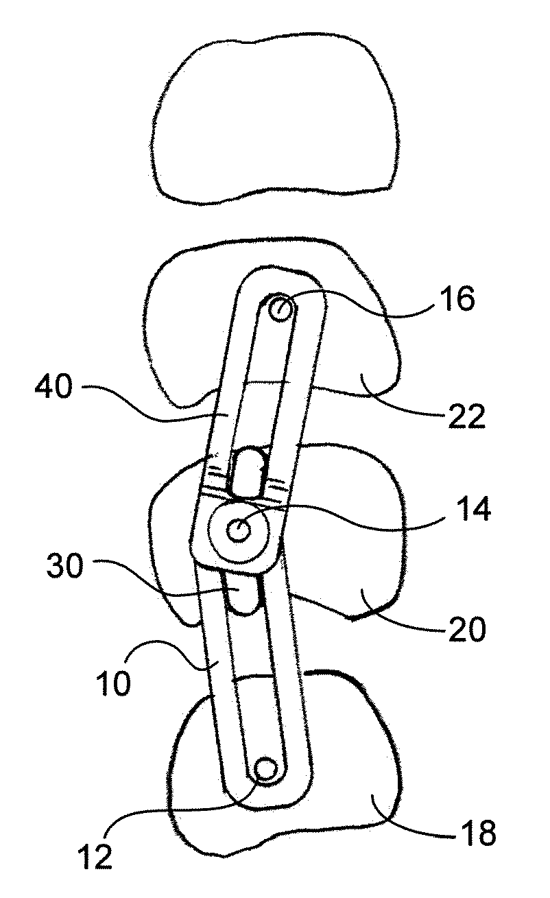
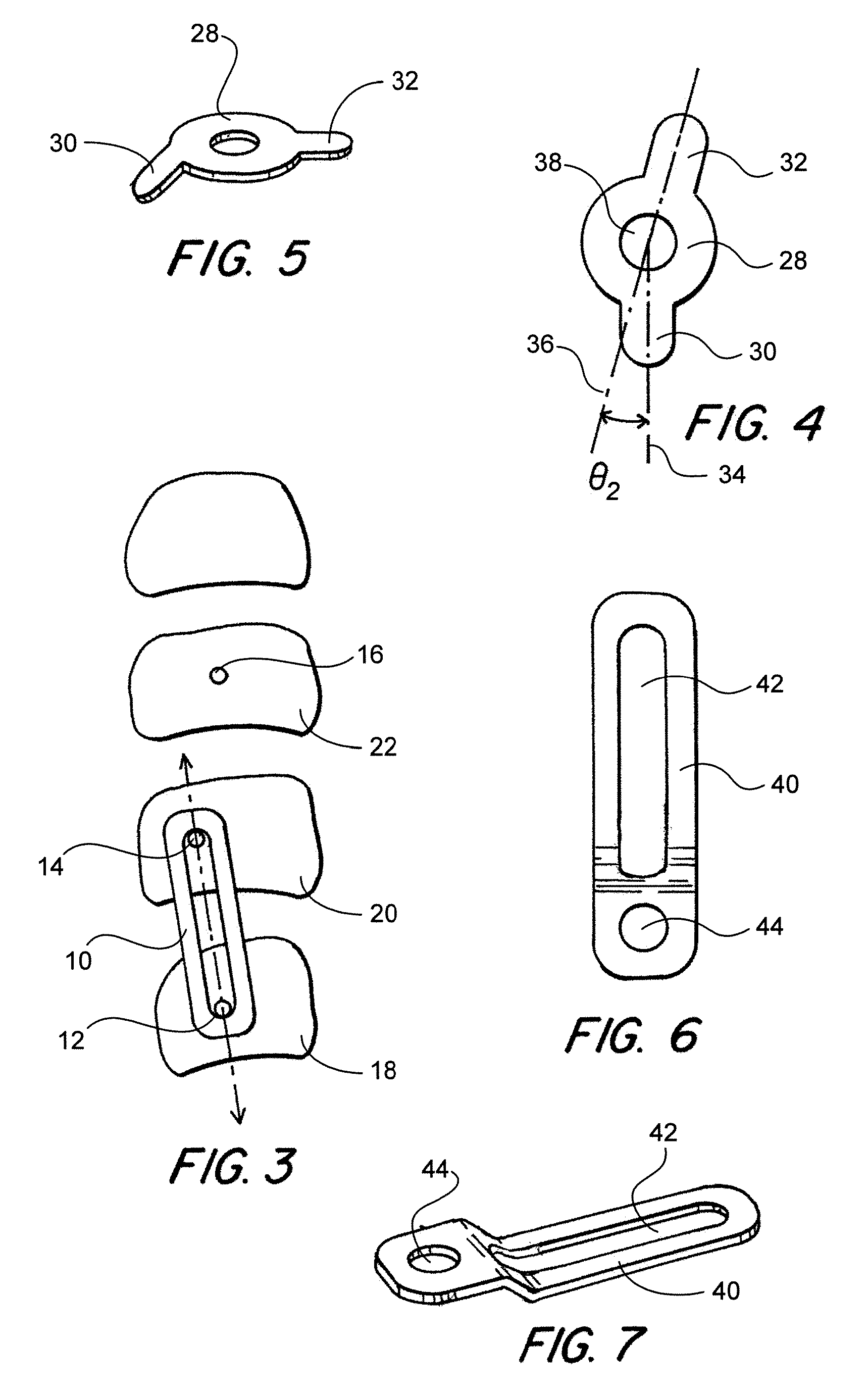
[0033]A problem with current systems is illustrated in FIG. 2 where pedicle screws 12, 14, 16 are shown inserted in vertebrae 18, 20, 22 respectively. As seen in FIG. 2, pedicle screws 12, 14 form a first plane 24, while pedicle screws 14, 16 form a second plane 26 that is off set from the first plane 24 by an angle θ1. However, prior art devices are only capable of being installed in a straight line and can not accommodate medial or lateral offsets, or in this example, angle θ1. For example, in FIG. 3 first plate 10 is illustrated installed on pedicle screws 12, 14, however, due to the interconnections between prior art plates, a second pl...


PUM


Abstract

A system and method for facilitating the installation of spinals support members on consecutive vertebrae where the optimal positioning of screws does not form a straight line. The system includes a first plate spanning a first and second vertebrae, a second plate spanning the second vertebrae and a third vertebrae and an offset member coupling the first plate to the second plate at a defined angle to accommodate the anatomical variations of the patients vertebrae.

Description

FIELD OF THE INVENTION[0001]The invention relates to a spinal implant and more particularly, to a device for accommodating the particular anatomy of a patient's spine when multiple spinal implants are inserted.BACKGROUND OF THE INVENTION[0002]Spinal implants have been utilized for a number of years and typically comprise plates or rods affixed to the spine. For any number of reasons, a joint can deteriorate requiring an implant be inserted to various vertebrae.[0003]A common practice has been to provide a pedicle screw in the individual vertebrae and attach a plate spanning the distance therebetween to stabilize the joint and maintain a set distance between the two vertebrae. The goal is to create / maintain normal anatomic relationship of two adjacent vertebrae of the spine. Often the plate is provided with at least one slot allowing for adjustment of the distance between the vertebrae before the implant is secured to the individual pedicle screws. The plate typically comprises a rig...

Claims


Application Information

Patent Timeline
Patent Type & Authority Applications(United States)
IPC IPC(8): A61B17/70A61B17/58
CPCA61B17/7059Y10S606/902Y10S606/901Y10S606/903
Inventor LIEPONIS, JONAS V.
Owner LIEPONIS JONAS V
Why Eureka
Try Eureka