Customizable light bulb changer

Inactive Publication Date: 2008-12-11
WAGIC
View PDF99 Cites 7 Cited by
  • Summary
  • Abstract
  • Description
  • Claims
  • Application Information

AI Technical Summary

Benefits of technology

[0010]In some embodiments, the present invention is adapted to permit a user to easily switch the clasping mechani

Problems solved by technology

One such problem is accessibility.
Overhead lights are purposefully positioned out of reach to minimize risks associated with heat burns and unintentional contact which could result in globe glass breakage; furthermore, many lights are recessed within their fixtures, limiting physical access to only a small portion of the bulb.
Another problem stems from the variety of angles from which bulbs must be extracted and replaced from these remote locations, such as from chandeliers and hanging light arrangements.
Another problem is the adjustability of the handle to reach light bulbs at varying distances.
Other problems arise from the need to apply force to the bulb and lighting fixture: too much force can cause damage to the bulb or fixture, or even bodily injury.
Further, the handle in this patent does not have a flexible arm for reaching light bulbs that are at an angle.
However, the device taught by Maki, by having a fixed rod, does not allow the user to adjust the rod to different heights.
T

Method used


Image

  • Customizable light bulb changer
  • Customizable light bulb changer
  • Customizable light bulb changer

Examples


Embodiment Construction

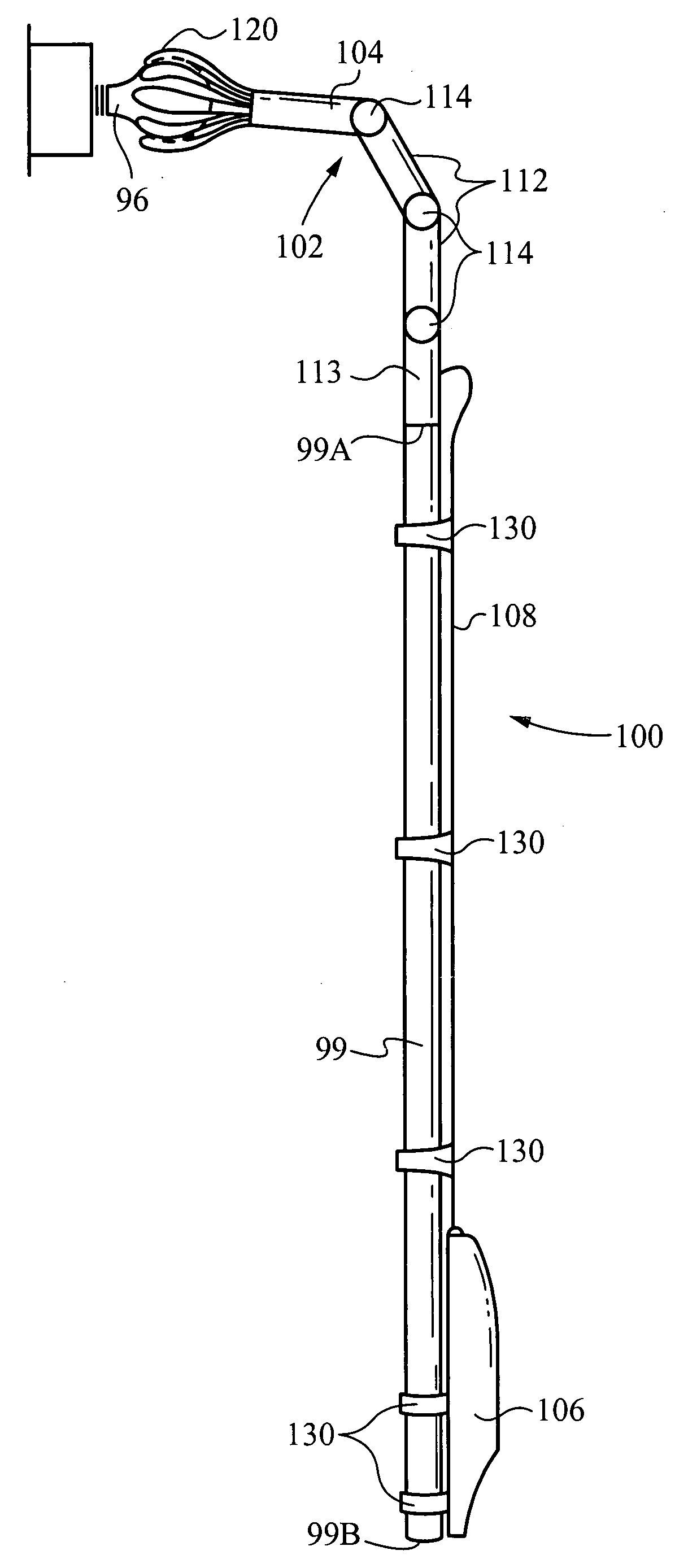
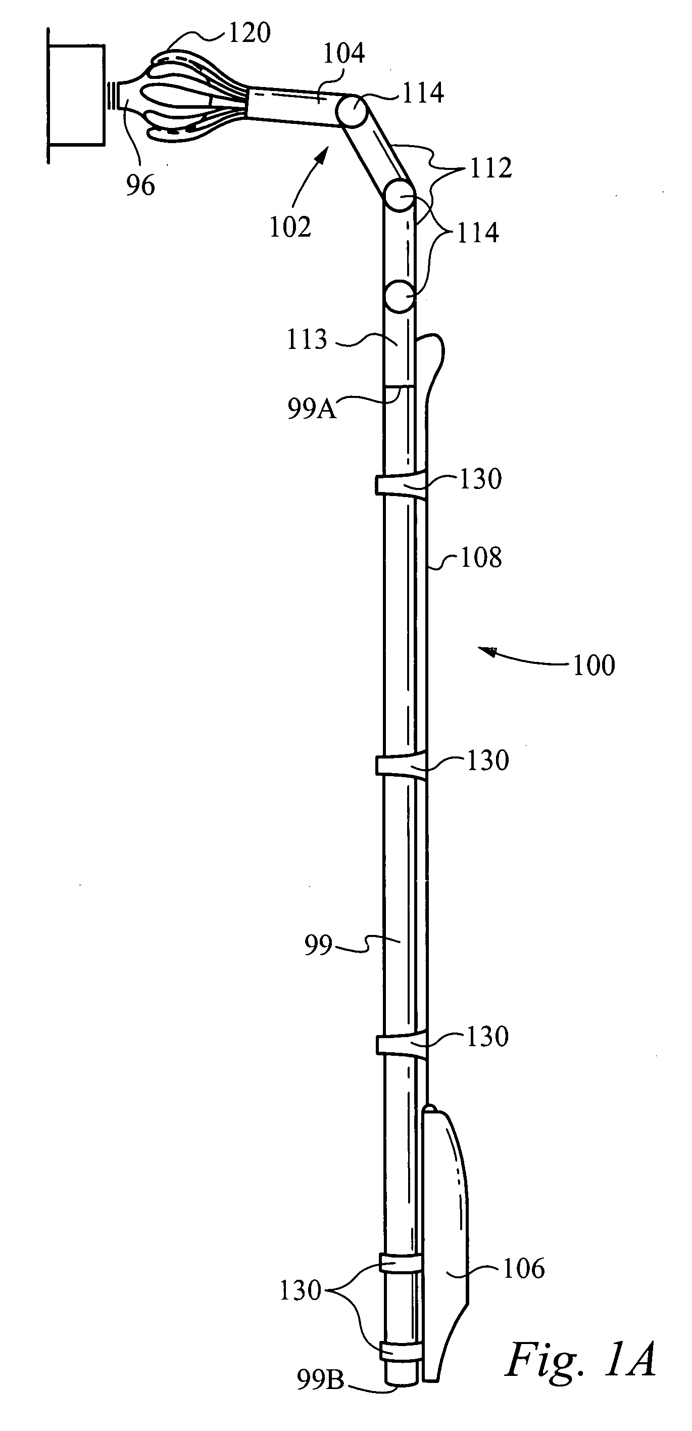
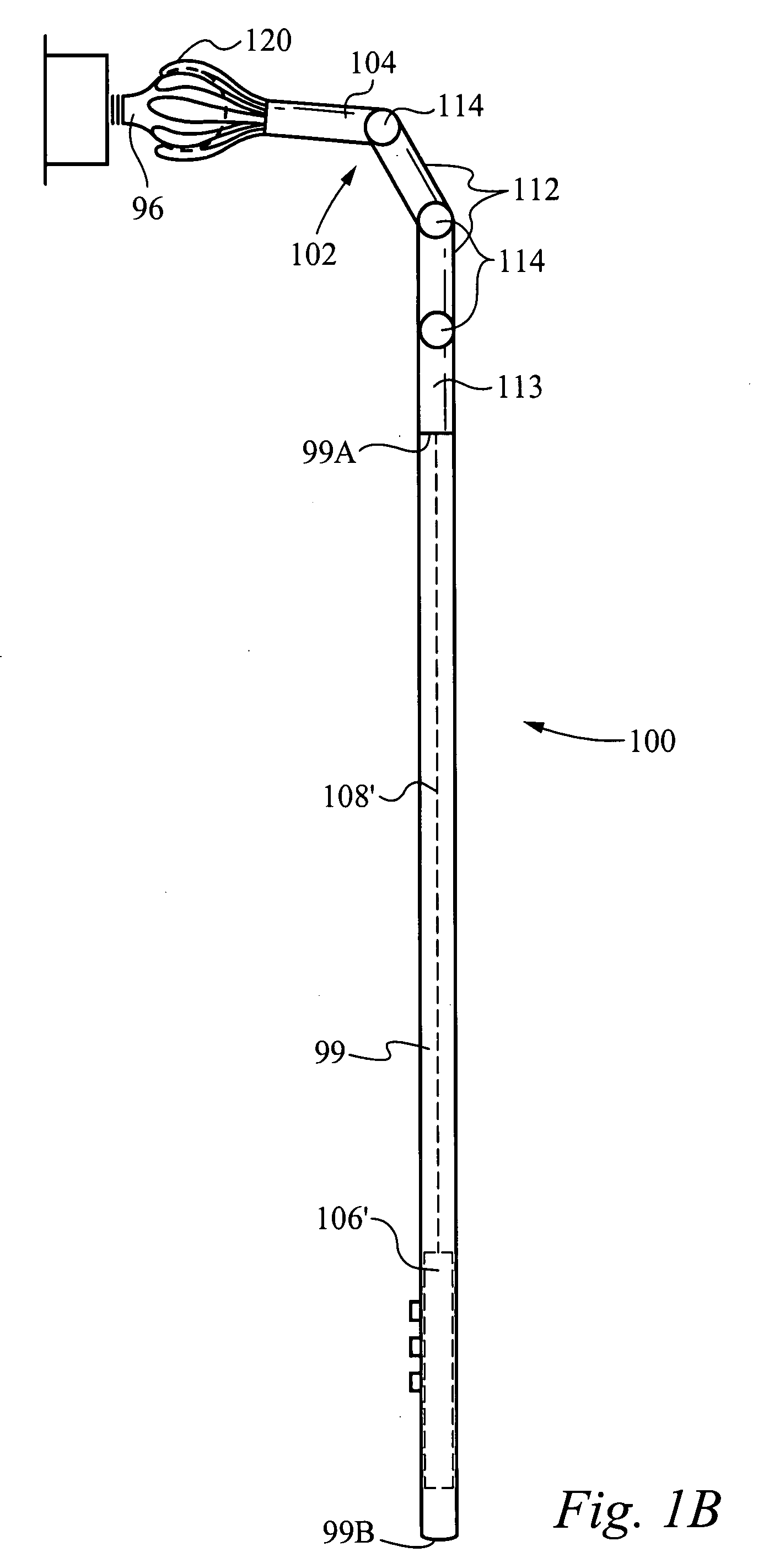
[0049]FIG. 1A illustrates a side view of an alternative embodiment of the motorized light bulb changer device with pole in accordance with the present invention. Generally, the motorized light bulb changer 100 includes a clasping mechanism 102 having a set of fingers 120, a motor unit 104, an arm unit 112 having a pair of arm members 112A and 112B (FIG. 2) and a connecting arm 113. In addition, the light bulb changer 100 includes a drive or power unit 106, whereby the drive unit 106 is coupled to the clasping mechanism 102 by a cable 108. As will be described in detail below, in the alternative embodiment of the present invention, the drive unit 106 communicates wirelessly to control the self-powered clasping mechanism 102. The motorized light bulb changer 100 shown in FIG. 1A is coupled to a pole 99 which allows the user to change light bulbs 96 held at a variety of angles and heights, that are otherwise inaccessible from ground level. In some embodiments the length of the pole 99 ...


PUM


Abstract

A light bulb changing tool comprises a holding structure configured to engage a light bulb. In some embodiments, the holding structure includes a suction cup configuration and in some embodiments, the holding structure includes a creased gripping configuration. An interconnect is configured to couple the holding structure with an arm member. The interconnect includes a receiving member for receiving a protruding member of the holding structure. In some embodiments, a securing member is included for securing the protruding member with the receiving member. The arm member is configured for positioning the holding structure in a desired configuration to engage the light bulb.

Description

RELATED APPLICATIONS[0001]This Patent Application is a continuation-in-part of co-pending U.S. patent application Ser. No. 11 / 345,710 filed on Feb. 1, 2006 and entitled “CUSTOMIZABLE LIGHT BULB CHANGER WITH SUCTION CUP AND CONTROL,” which is a continuation-in-part of co-pending U.S. patent application Ser. No. 10 / 841,286 filed on May 7, 2004 and entitled “CUSTOMIZABLE LIGHT BULB CHANGER”, which is a continuation-in-part of co-pending U.S. patent application Ser. No. 10 / 823,522 filed on Apr. 12, 2004 which is a continuation of U.S. application Ser. No. 10 / 218,404 filed on Aug. 12, 2002, titled “MOTORIZED LIGHT BULB CHANGER”, which are all hereby incorporated by reference.FIELD OF THE INVENTION[0002]The present invention relates to a remote access tool. More specifically, the present invention relates to a customizable light bulb changer designed to remove and replace light bulbs of various sizes, shapes, and configurations which are held at a variety of angles and heights and are oth...

Claims


Application Information

Patent Timeline
IPC IPC(8): H01K3/32
CPCH01K3/32H01J9/003B25B11/007B25B21/002B25G1/04F21V21/36
Inventor JOHNSON, RONALD L.GALLEGOS, ROBERT J.ESCOBAR, STEVEN SIMASHUDSON, ANDERS SCOTRUIZ, IDRISS MANSOURI-CHAFIKLOCKHART, YUGEN PATRICKWILSON, HOWARD ALLENCOLTON, ERIC M.
Owner WAGIC
Why Eureka
Try Eureka