
IC card comprising a main device and an additional device

Active Publication Date: 2008-12-11
STMICROELECTRONICS INT NV
View PDF7 Cites 190 Cited by
  • Summary
  • Abstract
  • Description
  • Claims
  • Application Information

AI Technical Summary

Benefits of technology

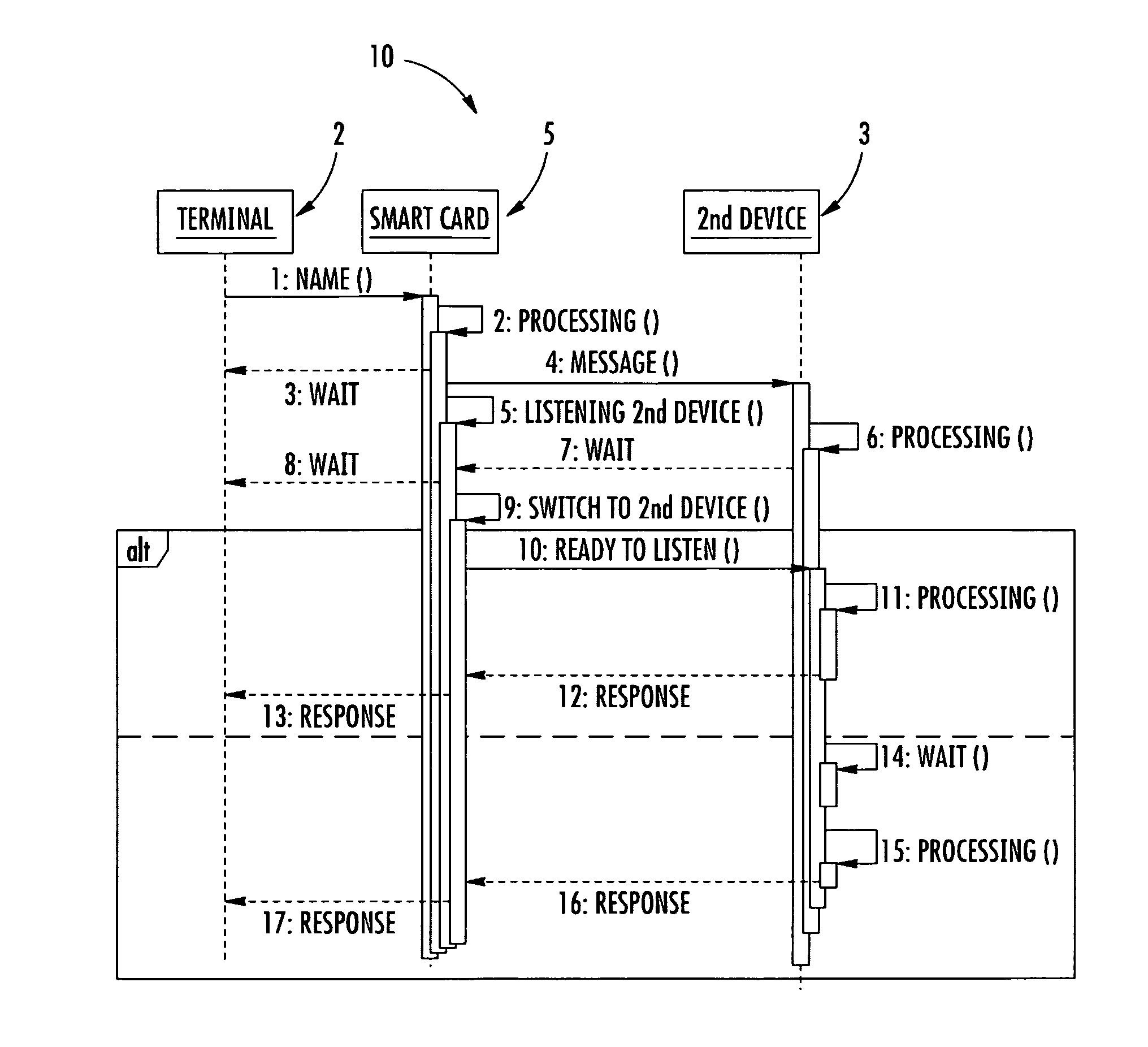
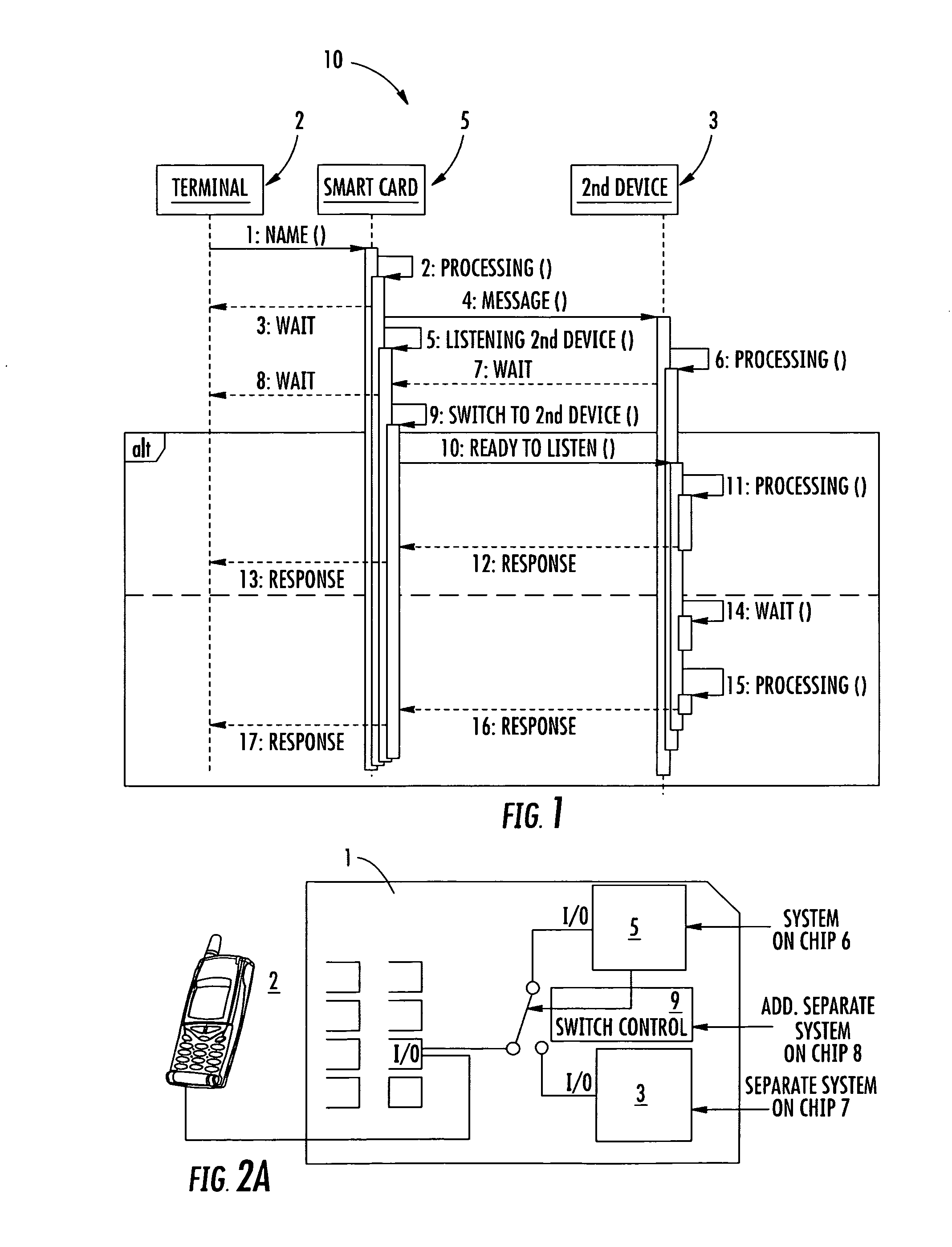
[0007]The approach on which the present invention is based, is that of providing an IC Card comprising a main device intended to be connected to a read write device for transmission of data over the I / O contact pad and comprising an additional device intended to communicate with the main device over the I / O contact pad for a transmission of secondary data. More particularly, the approach is that of providing a switch control for selectively switching the I / O contact pad for a transmission of main data between the main device and the read write device or for a transmission of secondary data between the main device and the additional device, avoiding interruption of the transmission of main data and secondary data and safeguarding the ISO 7816-3 communication protocol between the read-write device and the main device.
[0009]Advantageously, the communication between the additional device and the main device does not affect the communication between the main device and the read-write device, based on the ISO 7816-3 communication protocol. Advantageously, the main device may communicate with the additional device, overcoming the disadvantage that limits its use as a slave device with respect to the read-write device. Advantageously, the additional device may be provided with an additional communication protocol for communicating with an external device, so that the main device may receive data not only directly from the read write device but also from the external device, through the additional device.

Problems solved by technology

A disadvantage of such IC Card is that it may communicate only with the read write device, since it is powered by the read write device and, when powered, it may transmit data only over the I / O contact pad that is the unique channel available for communication.
Moreover, the IC Card cannot establish a secondary communication with another device since it cannot use the I / O contact pad for the secondary communication, without damaging the ISO 7816 communication protocol with the read write device.

Method used


Image

  • IC card comprising a main device and an additional device
  • IC card comprising a main device and an additional device
  • IC card comprising a main device and an additional device

Examples


Embodiment Construction

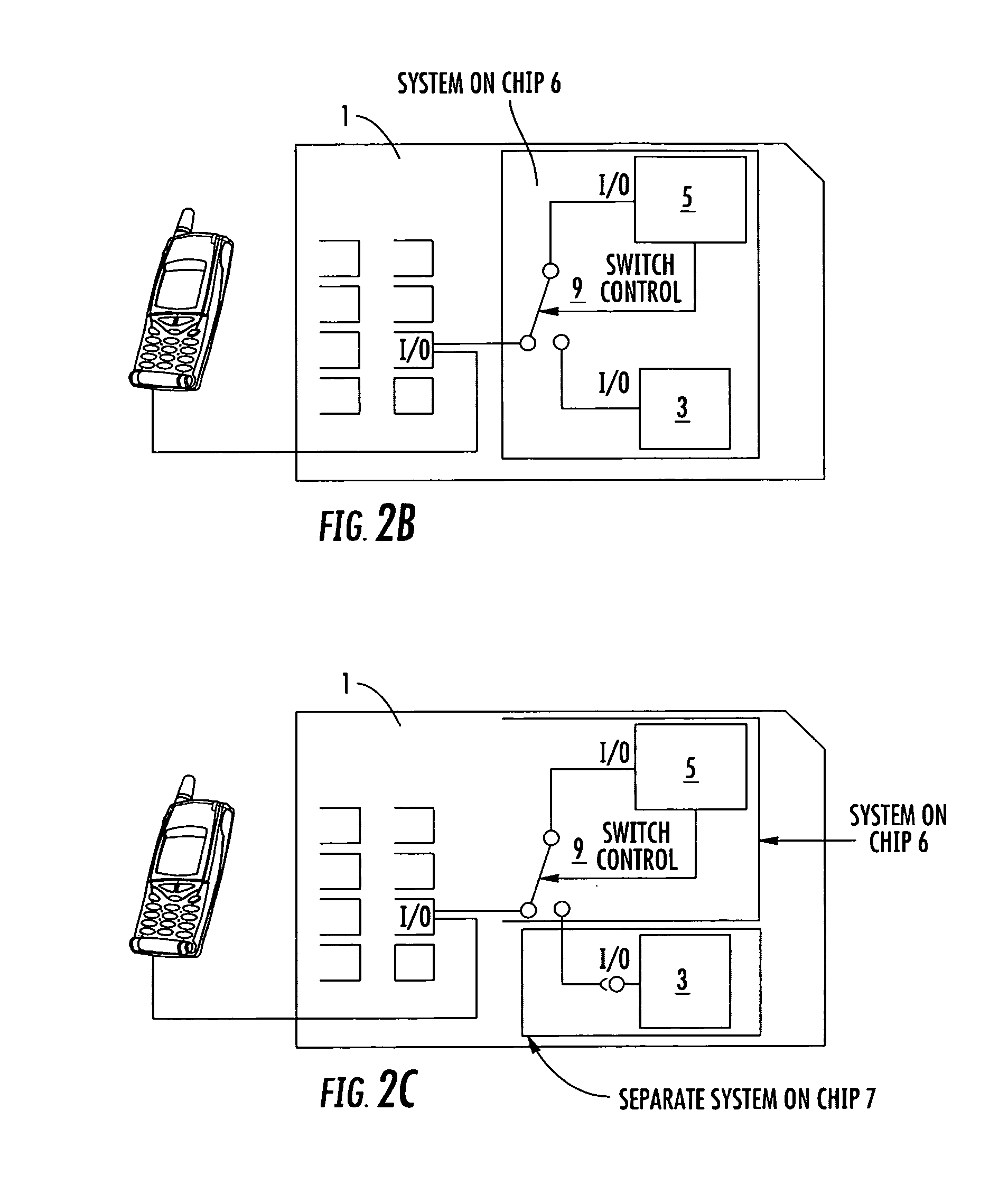
[0016]With reference to the annexed drawings, an IC Card is schematically shown and globally indicated with numeral reference 1. The IC Card 1 comprises at least one memory unit, one processor and a plurality of contact pads for a connection with a read-write device 2. The processor and the memory unit of the IC Card 1 are for example integrated in a System on Chip 6 and they are hereinafter globally indicated as a main device 5 of the IC Card 1.

[0017]The connection between the read-write device 2 and the main device 5, hereinafter indicated as main interconnection, is established via an I / O contact pad of the contact pads. A transmission of data between the read-write device 2 and the main device 5, also indicated as transmission of main data, is executed over the I / O contact pad. More particularly, the transmission of main data is based on a master / slave communication wherein the read-write device 2 is the master and sends commands to the main device 5 while the main device 5 is t...


PUM


Abstract

The IC Card includes a main device having a microprocessor and a memory unit, and an I / O contact pad for a connection between the main device and a read write device, also referred to as a main interconnection. The IC card also includes additional device connectable to the main device via a secondary interconnection including the I / O contact pad, and a switch control for selectively switching between the main interconnection, for a transmission of data between the read write device and the main device, and the secondary interconnection, for a transmission of data between the main device and the additional device.

Description

FIELD OF THE INVENTION[0001]The present invention relates to an integrated circuit (IC) Card including a microprocessor and a memory unit (generally referred to as the main device), and an input / output (I / O) contact pad for a connection between the main device and a read write device (also referred to as the main interconnection). The present invention also relates to a communication method for the above type IC Card.BACKGROUND OF THE INVENTION [0002]As it is well known, an IC Card includes a main device, including a processor and a memory portion, and a plurality of contact pads. The main device may be connected to a read-write device via a main interconnection including the contact pads. According to the ISO 7816-3 standard, the read-write device and the main device may communicate in a half duplex mode, sending and receiving data to and from the read-write device over an I / O contact pad of the main interconnection.[0003]In particular, the IC Card is an electrically passive compon...

Claims


Application Information

Patent Timeline
IPC IPC(8): G06K19/077G06F13/40G06F13/00
CPCG06K19/07G06K19/0723
Inventor MUSELLA, ENRICOSORBO, UMBERTO
Owner STMICROELECTRONICS INT NV
Learn More