Fusing device and image forming apparatus having the same

a technology of fusing device and image forming apparatus, which is applied in the direction of electrographic process apparatus, instruments, optics, etc., can solve the problems of fusing device of belt type, development of high-speed image forming apparatus, and meeting the requirements of fast heating and good fusing performance, so as to prevent damage to the heating portion

Active Publication Date: 2008-12-11
HEWLETT PACKARD DEV CO LP
View PDF5 Cites 48 Cited by
  • Summary
  • Abstract
  • Description
  • Claims
  • Application Information

AI Technical Summary

Benefits of technology

[0012]The present general inventive concept provides a fusing device having a nip a

Problems solved by technology

However, the currently available roller or belt type fusing device are obstacles to the development of a high speed image forming apparatus, because it does not meet the requirements for fast heating and good fusing performance.
However, because the heating roller 20 has a high heat capacity and the heating part 30 has to heat the entire heating roller 20, w

Method used


Image

  • Fusing device and image forming apparatus having the same
  • Fusing device and image forming apparatus having the same
  • Fusing device and image forming apparatus having the same

Examples


second embodiment

[0073]By use of the nip spring for the nip forming portion 340A, the fusing device according to the embodiment as illustrated in FIG. 7 can provide further improved fusing performance, because it can provide not only the thermal effect by the nip plate as in the second embodiment, but also the controlled pressure distribution over the nip areas (N) by the nip spring.

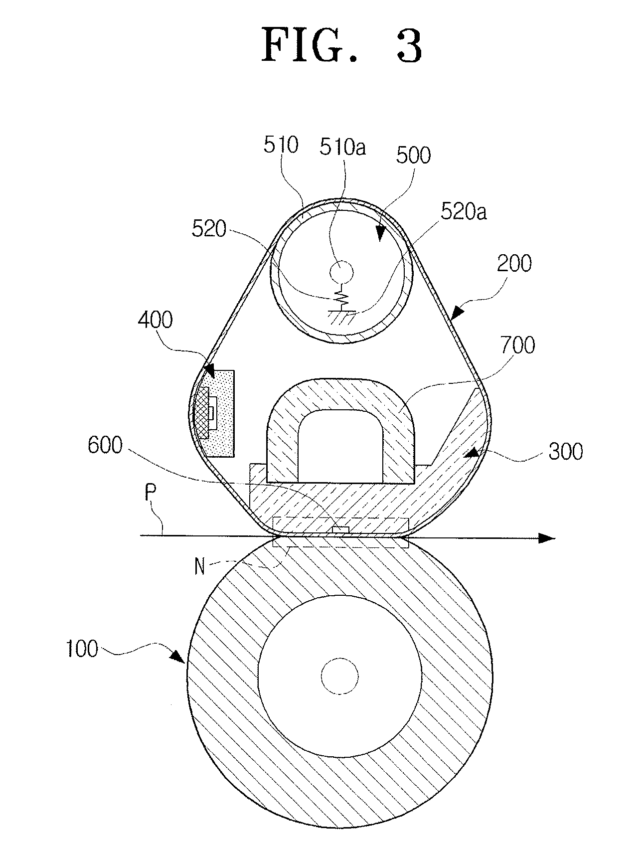
[0074]FIG. 9 is a cross section view illustrating a fusing device according to another exemplary embodiment of the present general inventive concept. Referring to FIG. 9, the fusing device has almost the same structure as that of the embodiment as illustrated in FIG. 3, except for a heating member 400 which is formed integrally with a nip forming member 300B. Throughout the description set forth below, the like elements will be referred to by the same reference numerals, and these will not be explained in detail for the sake of brevity.

[0075]The nip forming member 300B includes first and second guide portions 321 and 320...

fourth embodiment

[0077]FIG. 10 is a cross section view illustrating a fusing device according to another exemplary embodiment of the present general inventive concept. Referring to FIG. 10, the fusing device has almost the same structure as that of the embodiment illustrated in FIG. 9, except for a nip forming member 300C which is formed differently from that of the Throughout the description set forth below, the like elements will be referred to by the same reference numerals, and these will not be explained in detail for the sake of brevity.

[0078]The nip forming member 300C according to the present embodiment of the present general inventive concept includes a nip support portion 350 and a nip forming portion 360. The nip support portion 350 includes a mount space 351, and first and second guide portions 321 and 320 extending towards the upstream and downstream sides of the nip areas (N) to guide the fusing belt 200. The nip forming portion 360 is received in the mount space 351 so that the nip f...


PUM


Abstract

A fusing device includes a pressing member, a belt member to rotate in contact with the pressing member, a nip forming member to support the belt member so that nip areas are formed on the pressing member and the belt member at contacting portions thereto, a heating member disposed away from the nip areas, to heat the belt member, and a tension application member to stiffen the belt member so that the heating member is tightly contacted with the belt member. The heating member includes a plate type heating element which is arranged at an upstream side of the nip areas, and to contact an inner circumference of the belt member, in an advancing direction of the fusing belt. The effective width of then nip areas increases, and the increased pressure is exerted to the nip areas, because the fusing belt enters a location where the nip areas are formed in a heated state. Furthermore, heating efficiency of the fusing belt is increased, because the fusing belt is heated while in a tight contact with the heating member. As a result, fusing performance is enhanced.

Description

CROSS-REFERENCE TO RELATED APPLICATIONS[0001]This application claims priority under 35 U.S.C. § 119 (a) from of Korean Patent Application No. 10-2007-0055082, filed on Jun. 5, 2007, in the Korean Intellectual Property Office, the disclosure of which is hereby incorporated herein in its entirety by reference.BACKGROUND OF THE INVENTION[0002]1. Field of the Invention[0003]The present general inventive concept relates to an image forming apparatus, and more particularly, to a fusing device to fix a developer image onto a recording medium, and an image forming apparatus having the same.[0004]2. Description of the Related Art[0005]Generally, an image forming apparatus such as a printer, a copier, a scanner, a multi-function unit (MFU), or a facsimile, employs a fusing device to fix a developer image onto a recording medium after the developer image is transferred onto the recording medium by a transfer device. The fusing device is mainly classified into roller type and belt type devices....

Claims


Application Information

Patent Timeline
IPC IPC(8): G03G15/20
CPCG03G15/2053G03G2215/2038G03G15/14G03G15/2028G03G15/2064G03G2215/2035
Inventor SHIN, SU-HOKIM, TAE-HOONLEE, DONG-WOOKIM, TAE-GYU
Owner HEWLETT PACKARD DEV CO LP
Why Eureka
Try Eureka