Infrared encoding of security elements using standard xerographic materials with distraction patterns

a technology of xerographic materials and infrared encoding, which is applied in the direction of photosensitive materials, instruments, electrographic processes, etc., can solve the problems of variable data printing arrangement, special inks and materials are often difficult to incorporate into electro-photographic or other non-impact printing systems, etc., and achieve minimal system overhead requirements and storage requirements.

Active Publication Date: 2008-12-11
XEROX CORP
View PDF44 Cites 40 Cited by
  • Summary
  • Abstract
  • Description
  • Claims
  • Application Information

AI Technical Summary

Benefits of technology

[0004]It is desirable to have a way to provide for the detection of counterfeiting, illegal alteration, and / or copying of a document, most desirably in a manner that will provide document security and which is also applicable for digitally generated documents. It is desirable that such a solution also have minimum impact on system overhead requirements as well as minimal storage requirements in a digital processing and printing environment. Additionally, it is particularly desirable that this solution be obtained without physical modification to the printing device and without the need for costly special materials and media.
[0012]Disclosed in embodiments herein is an infrared mark indicator comprising an infrared reflective substrate, a first spatial color pattern and a second spatial color pattern printed as an image upon the substrate. The first spatial color pattern is further comprised of a first colorant mixture and a second colorant mixture arranged in a first repeating spatial pattern, the resultant first spatial color pattern having a property of high infrared reflectance. The second spatial color pattern is printed as an image upon the substrate in substantially close spatial proximity to the printed first spatial color pattern. The second spatial color pattern is further comprised of a third colorant mixture and a forth colorant mixture in a second repeating spatial pattern, the resultant second spatial color pattern having a property of low infrared reflectance, and a property of low contrast against the first spatial color pattern. The arrangement is such that the resultant printed substrate image suitably exposed to an infrared illuminant, will yield a discernable pattern evident as an infrared mark to a suitable device.
[0015]Further disclosed in embodiments herein is an infrared mark indicator comprising an infrared reflective substrate, a first spatial color pattern and a second spatial color pattern printed as an image upon the substrate. The first spatial color pattern is further comprised of a first colorant mixture and at least a second colorant mixture arranged in a first repeating spatial pattern, the resultant first spatial color pattern having a first level of infrared reflectance. The second spatial color pattern is printed as an image upon the substrate in substantially close spatial proximity to the printed first spatial color pattern. The second spatial color pattern is further comprised of a third colorant mixture and at least a forth colorant mixture in a second repeating spatial pattern, the resultant second spatial color pattern having a second level of infrared reflectance, and a property of low contrast against the first spatial color pattern under normal illumination. The arrangement is such that the resultant printed substrate image suitably exposed to an infrared light source, will yield a discernable pattern evident to a suitable device as a infrared mark, by exhibiting a discernible first and second level of infrared reflectance.

Problems solved by technology

However, these special inks and materials are often difficult to incorporate into standard electro-photographic or other non-impact printing systems like solid ink printers, either due to cost, availability or physical / chemical properties.
This in turn discourages their use in variable data printing arrangements, such as for redeemable coupons or other personalized printed media for example.

Method used


Image

  • Infrared encoding of security elements using standard xerographic materials with distraction patterns
  • Infrared encoding of security elements using standard xerographic materials with distraction patterns
  • Infrared encoding of security elements using standard xerographic materials with distraction patterns

Examples


Embodiment Construction

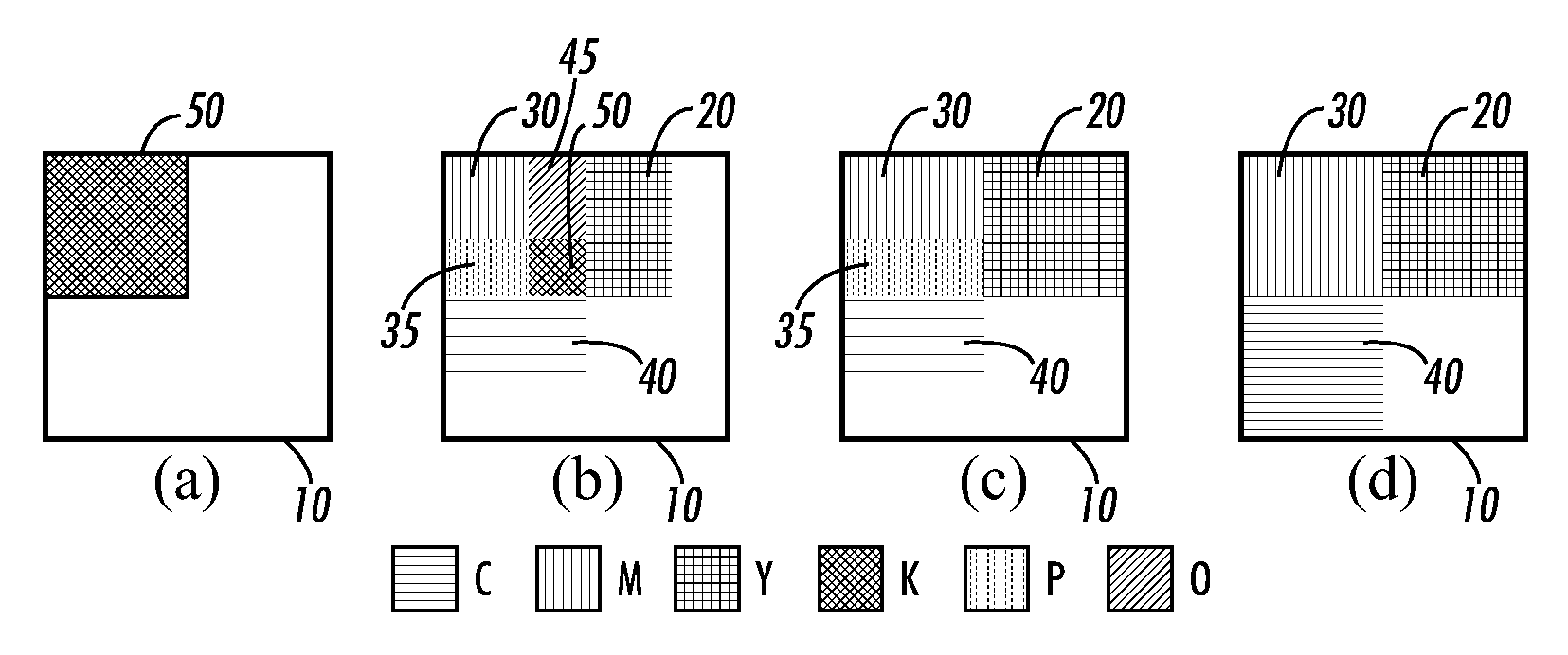
[0022]For a general understanding of the present disclosure, reference is made to the drawings. In the drawings, like reference numerals have been used throughout to designate identical elements. In describing the present disclosure, the following term(s) have been used in the description.

[0023]The term “data” refers herein to physical signals that indicate or include information. An “image”, as a pattern of physical light or a collection of data representing said physical light, may include characters, words, and text as well as other features such as graphics. A “digital image” is by extension an image represented by a collection of digital data. An image may be divided into “segments,” each of which is itself an image. A segment of an image may be of any size up to and including the whole image. The term “image object” or “object” as used herein is believed to be considered in the art generally equivalent to the term “segment” and will be employed herein interchangeably. In the e...


PUM

PropertyMeasurementUnit
spatial frequencyaaaaaaaaaa
coloraaaaaaaaaa
grayscale valueaaaaaaaaaa

Abstract

The teachings as provided herein relate to a watermark embedded in an image that has the property of being relatively indecipherable under normal light, and yet decipherable under infrared illumination when viewed by a suitable infrared sensitive device. This infrared mark entails in combination with at least one distraction pattern, a substrate reflective to infrared radiation, and a first colorant mixture and second colorant mixture printed as an image upon the substrate. The first colorant mixture layer in connection with the substrate has a property of strongly reflecting infrared illumination, as well as a property of low contrast under normal illumination against a second colorant mixture as printed in close spatial proximity to the first colorant mixture pattern, such that the resultant image rendered substrate suitably exposed to an infrared illumination, will yield a discernable image evident as a infrared mark to a suitable infrared sensitive device.

Description

CROSS-REFERENCE TO RELATED APPLICATIONS[0001]Cross-reference is made to the following application filed simultaneously herewith and incorporated by reference herein: Eschbach et al., U.S. patent application Ser. No. ______, filed simultaneously herewith, entitled “INFRARED ENCODING OF SECURITY ELEMENTS USING STANDARD XEROGRAPHIC MATERIALS” (Attorney Docket No. 20070029-US-NP).[0002]Cross-reference is made to the following applications which are incorporated by reference herein: Eschbach et al., U.S. patent application Ser. No. ______, filed simultaneously herewith, entitled “INFRARED ENCODING FOR EMBEDDING MULTIPLE VARIABLE DATA INFORMATION COLLOCATED IN PRINTED DOCUMENTS” (Attorney Docket No. 20070293-US-NP); Bala et al., U.S. patent application Ser. No. 11 / 382,897, filed May 11, 2006, entitled “SUBSTRATE FLUORESCENCE MASK FOR EMBEDDING INFORMATION IN PRINTED DOCUMENTS” (Attorney Docket No. 20050309-US-NP); Bala et al., U.S. patent application Ser. No. 11 / 382,869, filed May 11, 200...

Claims


Application Information

Patent Timeline
Patent Type & Authority Applications(United States)
IPC IPC(8): G03C1/00G03G13/00
CPCY10T428/24802G03G21/046
Inventor ESCHBACH, REINERBALA, RAJAMALTZ, MARTIN S.
Owner XEROX CORP
Why Eureka
Try Eureka