
Manufacturing method of semiconductor integrated circuit device

Inactive Publication Date: 2008-12-11
RENESAS ELECTRONICS CORP
View PDF9 Cites 4 Cited by
  • Summary
  • Abstract
  • Description
  • Claims
  • Application Information

AI Technical Summary

Benefits of technology

[0012]Advantageous effects of the typical aspect of the invention disclosed in the present application will be briefly described in the following:
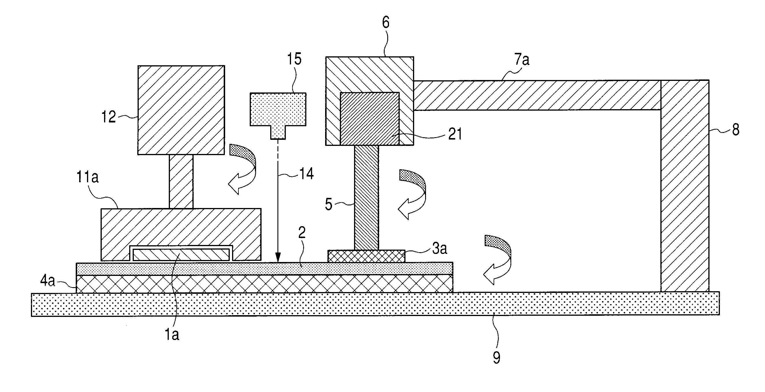
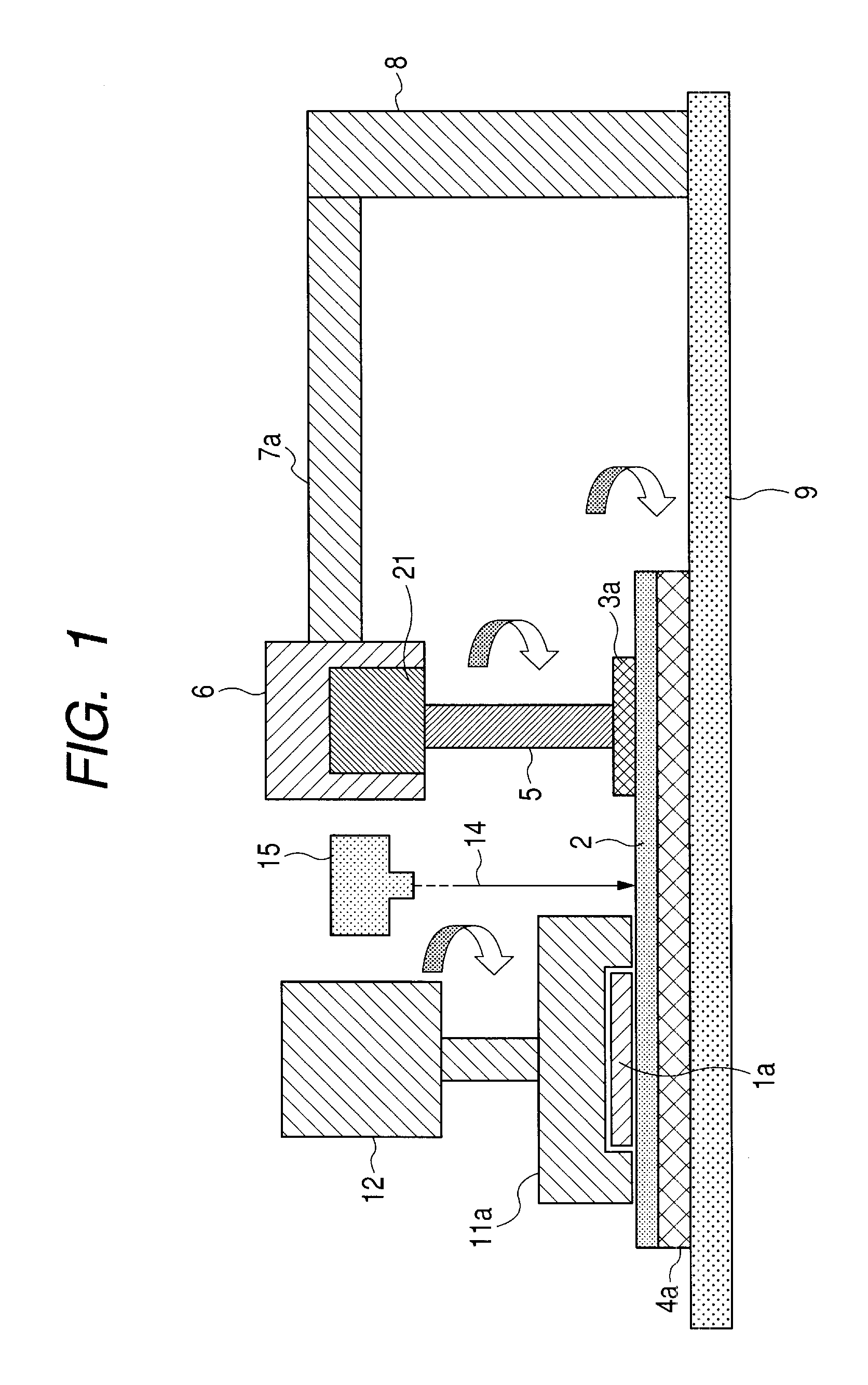
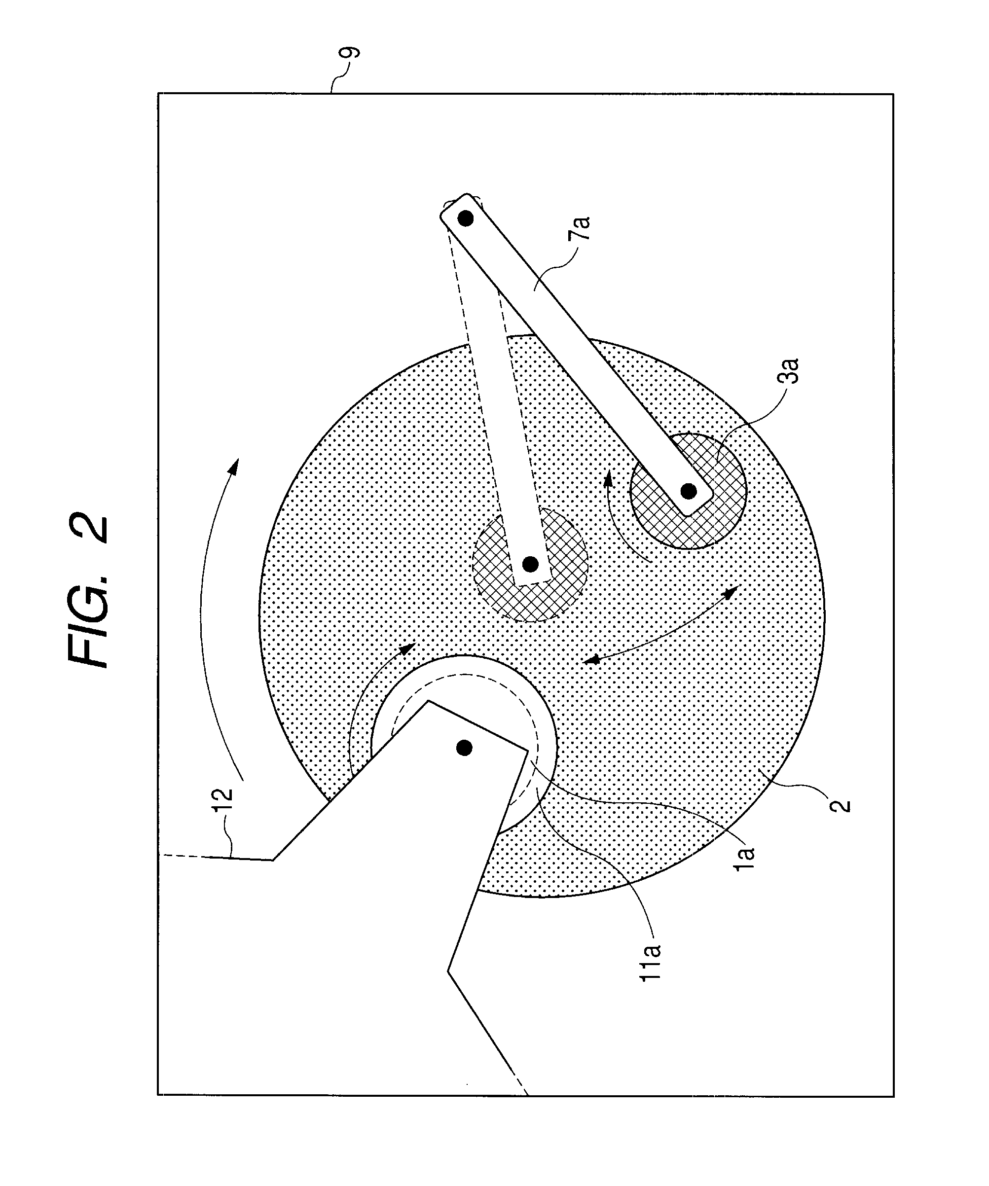
[0013]When the dresser operates, the height position of the dresser is measured, thereby detecting the abrasion amount or the thickness of the polishing pad indirectly; therefore, the physical quantity can be measured without polluting the polishing pad with a sensor or any other member.

Problems solved by technology

However, the polishing pad is relatively high in price, and it is necessary to avoid exchanging the pad wastefully.
However, according to ordinary measurement thereof through light, the presence of slurry hinders the precise measurement.
According to a contact type sensor, a problem that pollutants elute out is caused.

Method used


Image

  • Manufacturing method of semiconductor integrated circuit device
  • Manufacturing method of semiconductor integrated circuit device
  • Manufacturing method of semiconductor integrated circuit device

Examples


Embodiment Construction

[Summary of Embodiments]

[0028]First, typical embodiments of the invention disclosed in the present application will be summarized in the following:[0029]1. A manufacturing method of a semiconductor integrated circuit device, comprising the steps of: (a) forming a first member layer over a first main surface of a wafer; and (b) applying chemical mechanical polishing to the first member layer in a chemical mechanical polishing machine, wherein the step (b) comprises the substeps of: (i) pressing a rotating dresser to a polishing pad, thereby carrying out dressing treatment; (ii) supplying a polishing slurry to the polishing pad while moving the pad and the wafer relatively in a state that the first main surface of the wafer is pressed to the polishing pad; and (iii) measuring the position of the dresser in the direction perpendicular to the surface of the polishing pad in the substep (i), thereby detecting the abrasion amount and the thickness of the polishing pad indirectly.[0030]2. ...


PUM

PropertyMeasurementUnit
Timeaaaaaaaaaa
Thicknessaaaaaaaaaa
Radiusaaaaaaaaaa

Abstract

A polishing pad used in a CMP step in the manufacture of a semiconductor integrated circuit device is relatively expensive; thus, it is necessary to avoid a wasteful exchange of the pad. Accordingly, it is important to measure the abrasion amount of this pad precisely. However, in ordinary measurement thereof through light, the presence of a slurry hinders the measurement. In measurement thereof with a contact type sensor, a problem that pollutants elute out is caused. In a CMP step in the invention, the height position of a dresser is measured while the dresser operates, thereby detecting the abrasion amount or the thickness of a polishing pad indirectly. In this way, the time for exchanging the polishing pad is made appropriate.

Description

BACKGROUND OF THE INVENTION[0001]The present invention relates to a technique useful for chemical mechanical polishing technique, which is generally called CMP technique, in a manufacturing method of a semiconductor integrated circuit device (or a semiconductor device).[0002]Japanese Unexamined Patent Publication No. 2000-271854 discloses a technique of measuring the flatness, the surface roughness, the elastic modulus, the porosity and other properties of a polishing pad of a CMP machine to use the measured properties to decide the time when the pad is exchanged, or the like.[0003]Japanese Unexamined Patent Publication No. Hei 11 (1999)-207572 or corresponding U.S. Pat. No. 5,934,974 discloses a system of monitoring the abrasion of a polishing pad of a CMP machine with a noncontact sensor while the machine operates, so as to instruct the exchange of the pad, or the like.[0004]Japanese Unexamined Patent Publication No. Hei 9 (1997)-290363 discloses a method of measuring the height o...

Claims


Application Information

Patent Timeline
IPC IPC(8): B24B49/12B24B7/20B24B53/00B24B49/10B24B49/18B24B53/017H01L21/304
CPCB24B49/12B24B53/017H01L21/304
Inventor ITO, YOSHINORI
Owner RENESAS ELECTRONICS CORP
Learn More