
Air flow measuring device

Active Publication Date: 2008-12-18
DENSO CORP
View PDF15 Cites 13 Cited by
  • Summary
  • Abstract
  • Description
  • Claims
  • Application Information

AI Technical Summary

Benefits of technology

[0007]In view of the foregoing problems, it is an object of the present invention to provide an air flow measuring device, which can prevent dust contained in air from colliding with a flow amount sensor.
[0008]It is another object of the present invention to provide an air flow measuring device, which can effectively reduce dust entering from a first sub-passage portion into a second sub-passage portion so as to restrict a collision of dust with a flow amount sensor.
[0010]Because the throttle portion is provided to gradually reduce a passage dimension of the first sub-passage portion in the second radial direction as toward the outlet of the first sub-passage portion, dust does not fly into the inlet of the second sub-passage portion even when the dust collides with the throttle portion. Accordingly, it can restrict the dust from entering into the second sub-passage portion, thereby preventing the dust from colliding with the flow amount sensor.

Problems solved by technology

In particular, when a thin film-like measuring element is used in the flow amount sensor 140, the measuring element is easily damaged by the collision with the dust.

Method used


Image

  • Air flow measuring device
  • Air flow measuring device
  • Air flow measuring device

Examples


Embodiment Construction

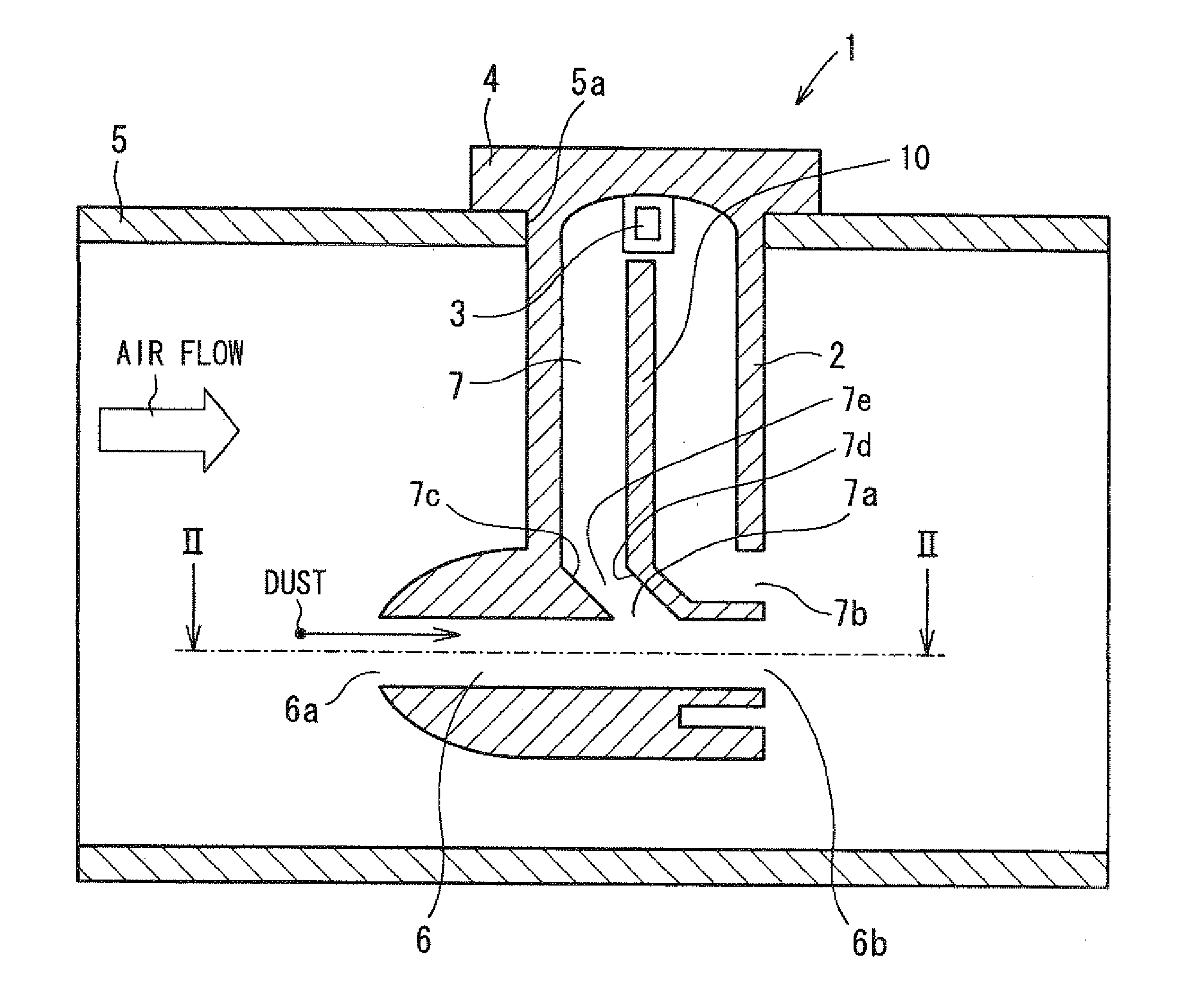
[0017]An air flow measuring device 1 of an embodiment will be now described with referent to FIGS. 1, 2A and 2B. For example, the air flow measuring device 1 can be used as an air flow meter for measuring a flow amount of intake air in an internal combustion engine for a vehicle. The air flow measuring device 1 includes a sensor body 2, a flow amount sensor 3 and a circular module 4.

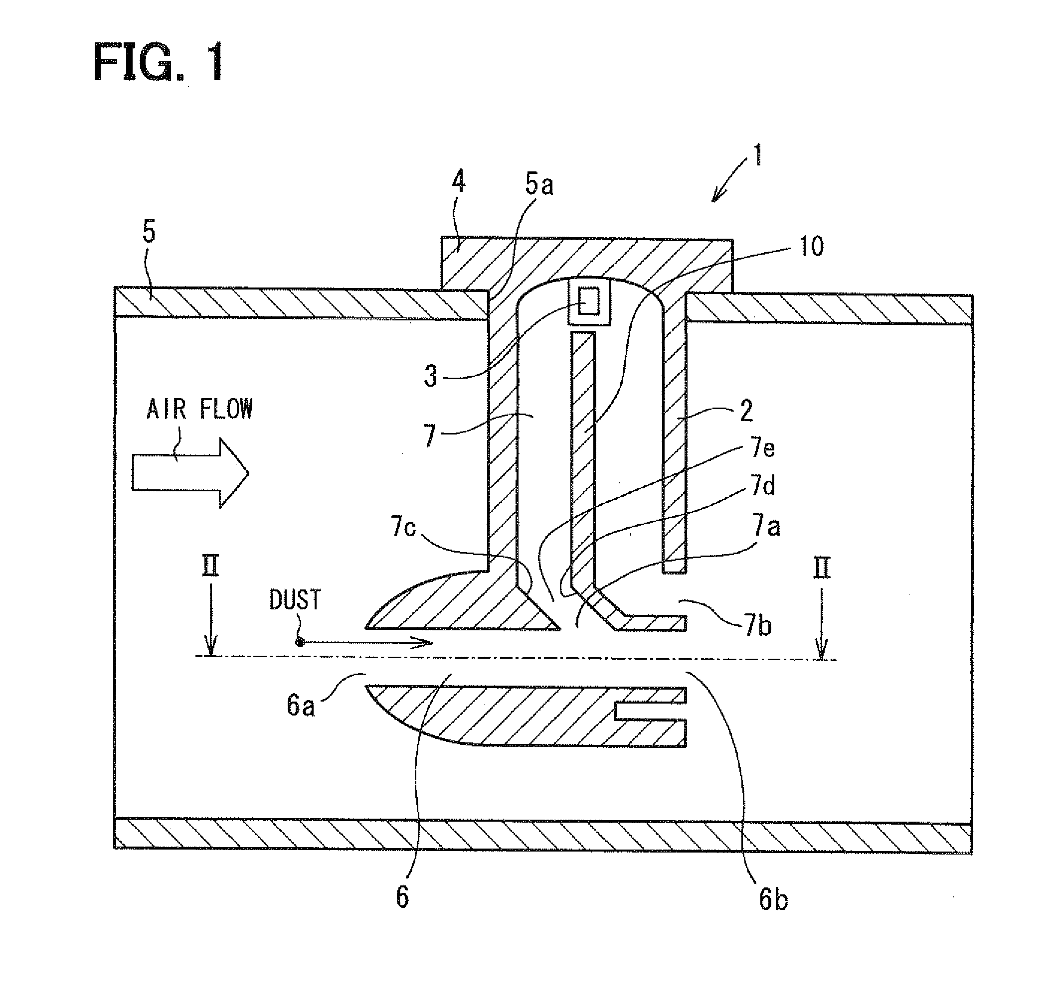
[0018]The sensor body 2 is inserted into an interior of an intake air duct 5 of the engine. Air flows into an intake air port of the engine through the intake air duct 5. The intake air duct 5 has an attachment hole portion 5a into which the sensor body 2 is fitted after the sensor body 2 is inserted into the interior of the intake air duct 5. The sensor body 2 is provided with a first sub-passage 6 into which a part of air flowing in the intake air duct 5 is introduced, and a second sub-passage 7 into which a part of air flowing in the first sub-passage 6 is introduced.

[0019]In the example of FIG. 1, ai...


PUM


Abstract

An air flow measuring device has a throttle portion provided in a first sub-passage, a second sub-passage branched from the first sub-passage at an upstream side of the throttle portion, and a flow amount sensor located in the second sub-passage. The second sub-passage is configured to introduce therein a part of air flowing in the first sub-passage, and an inlet of the second sub-passage is open into the first sub-passage at one side in a first radial direction perpendicular to a flow direction of air flowing in the first sub-passage. Furthermore, the throttle portion is provided to gradually reduce a passage dimension of the first sub-passage in a second radial direction, as toward an outlet of the first sub-passage. Here, the second radial direction is perpendicular to a surface defined by the first radial direction and the flow direction of air in the first sub-passage.

Description

CROSS REFERENCE TO RELATED APPLICATION[0001]This application is based on Japanese Patent Application No. 2007-157314 filed on Jun. 14, 2007, the contents of which are incorporated herein by reference in its entirety.BACKGROUND OF THE INVENTION[0002]1. Field of the Invention[0003]The present invention relates to an air flow measuring device having a first sub-passage configured to introduce therein a part of air flowing in an interior of a duct, a second sub-passage configured to introduce therein a part of air flowing in the first sub-passage, and a flow amount sensor located in the second sub-passage to measure a flow amount of air.[0004]2. Description of the Related Art[0005]An air flow measuring device described in U.S. Pat. No. 7,089,788 (corresponding to JP 2005-140753A) is provided for measuring a flow amount of intake air flowing into an internal combustion engine. As shown in FIG. 3, the air flow measuring device includes a sensor body 110 disposed in an intake air passage 1...

Claims


Application Information

Patent Timeline
IPC IPC(8): G01M15/00
CPCG01F1/6842
Inventor ENOMOTO, TAKASHIKITAHARA, NOBORU
Owner DENSO CORP
Features
  • Generate Ideas
  • Intellectual Property
  • Life Sciences
  • Materials
  • Tech Scout
  • Unparalleled Data Quality
  • Higher Quality Content
  • 60% Fewer Hallucinations
Learn More