Non-contact shock sensor

a shock sensor and non-contact technology, applied in the field of non-contact shock sensors, can solve problems such as irreversible destruction

Inactive Publication Date: 2008-12-18
SIEMENS HEALTHCARE GMBH
View PDF9 Cites 22 Cited by
  • Summary
  • Abstract
  • Description
  • Claims
  • Application Information

AI Technical Summary

Problems solved by technology

These are irreversibly destroyed if a correspondingly heavy impact has occurred.
The disadvantage of the devices according to the prior art however is that they m...

Method used


Image

  • Non-contact shock sensor
  • Non-contact shock sensor
  • Non-contact shock sensor

Examples


Embodiment Construction

[0027]The drawing is not true-to-scale. The same elements or elements with the same effect are provided with the same reference numbers.

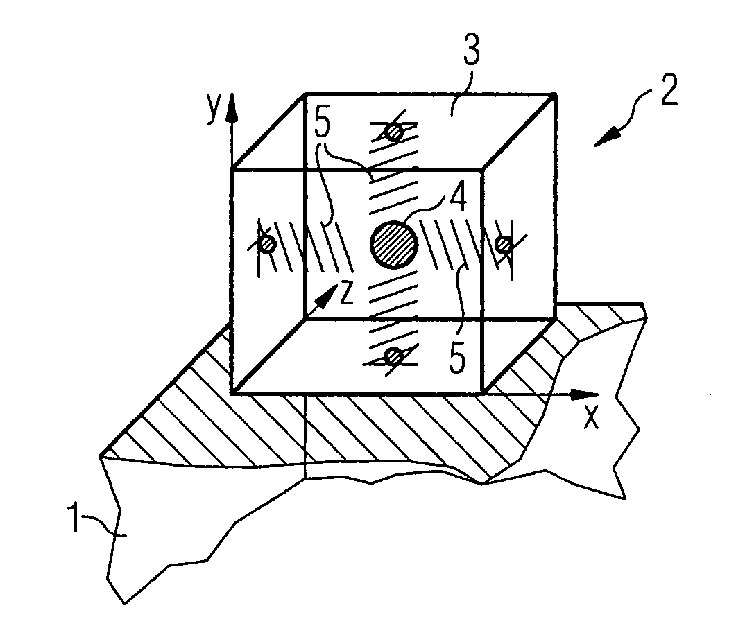
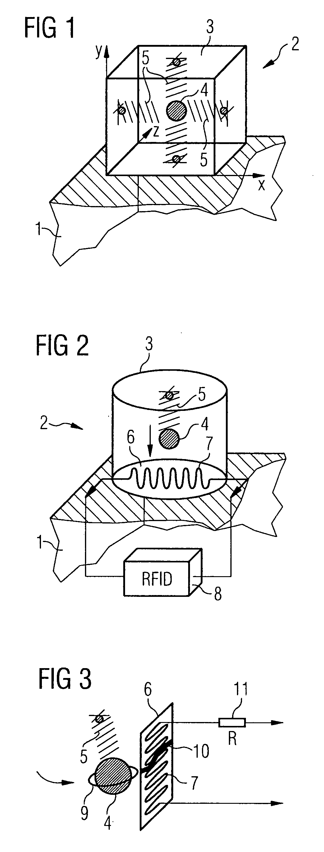
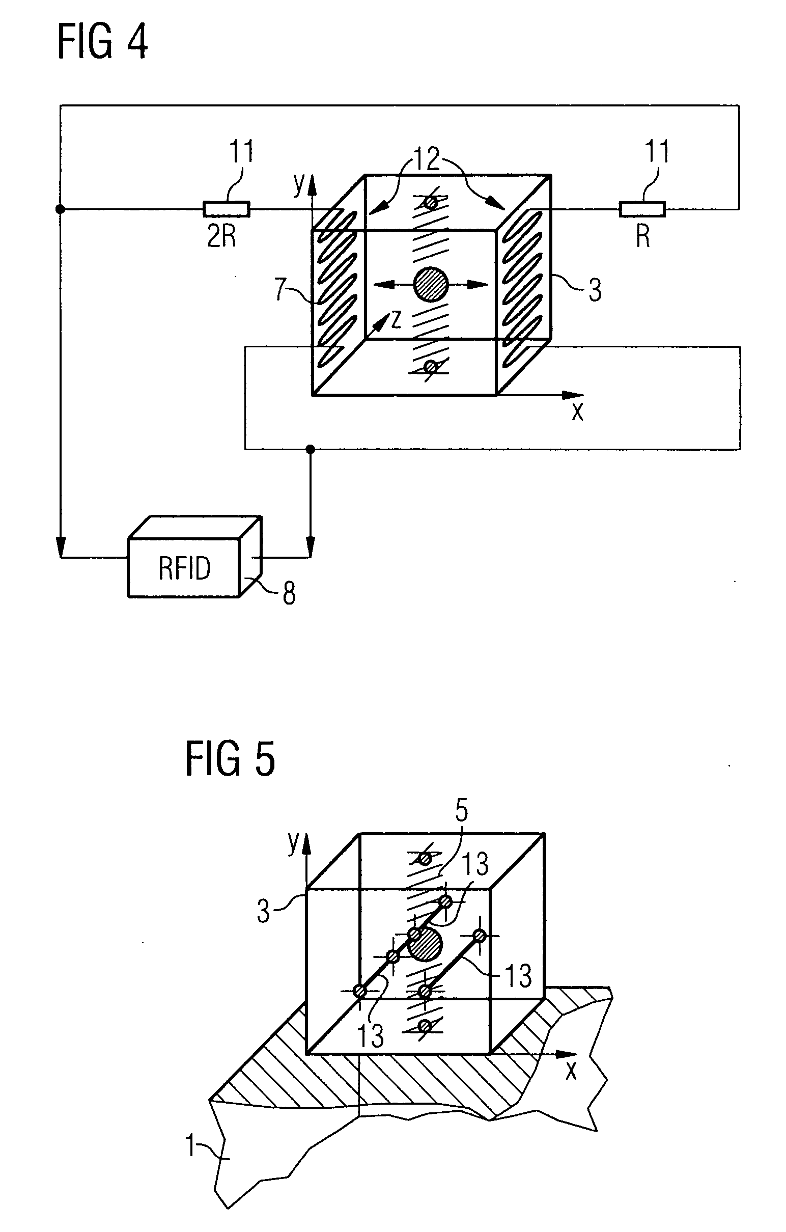
[0028]The principal of the invention is depicted schematically in FIG. 1. An acceleration sensor 2 is permanently attached to an object 1 for which it is also to be established retrospectively, as regards acceleration, whether a limit value has been exceeded or not. The term “permanently attached” in the context explained here means that there is no movement or only negligible relative movement between the object 1 and the acceleration sensor 2. In other words the acceleration which operates on the object operates with equal strength on the acceleration sensor 2 as well. The acceleration sensor 2 is made up of a support frame 3 and a movable mass 4 supported within this frame. The support frame 3 takes the form of a cube here although it is obvious to the person skilled in the art that it can have almost any form and be selected depending on the use...


PUM


Abstract

The invention relates to a sensor device for monitoring accelerations to which an object is subjected. In order to detect whether a value has exceeded or is below a threshold for the acceleration to which objects have been subjected in the past, i.e. without having visual contact with the sensor, the inventive sensor device includes an acceleration sensor, which is permanently linked to the object to be monitored, so that a relative movement between the acceleration sensor and the object is prevented, and an RFID transceiver for non-contact coupling of electrical energy into the acceleration sensor and for sending out radio signals as a function of the physical state of the acceleration sensor.

Description

CROSS REFERENCE TO RELATED APPLICATIONS[0001]This application claims priority of German application No. 10 2006 042 382.8 filed Sep. 08, 2006, which is incorporated by reference herein in its entirety.FIELD OF THE INVENTION[0002]The invention relates to the monitoring of physical parameters of objects during their transport and especially to a sensor device for accelerations, i.e. shocks to which transported items are subjected, in accordance with the claims.BACKGROUND OF THE INVENTION[0003]When goods are dispatched and transported it can be necessary, if these goods are fragile, for them to be protected from shocks. They must therefore be given a special protection during transport and it is important to be able to check at the destination or at particular times whether they have been subjected to too high an acceleration since the beginning of the transport process. Thus freight forwarders must be in a position to check the status of the goods when handing them over or to be able ...

Claims


Application Information

Patent Timeline
IPC IPC(8): G01P3/00
CPCG01P15/06G01P15/0891G01P15/135G01P15/18G06Q10/08H01H9/167H01H35/146H01H2300/066
Inventor GORTLER, SEBASTIANKAGERMEIER, ROBERTKUTH, RAINERLUDWIG, KLAUSWELLER, GERHARD
Owner SIEMENS HEALTHCARE GMBH
Why Eureka
Try Eureka