Signal measurement system and method for testing an RF component

a technology of signal measurement system and component, which is applied in the direction of transmission monitoring, receiver monitoring, instruments, etc., can solve the problems of unrepeatability, inefficiency, inconvenient testing, and inability to meet the needs of the subject antenna, so as to reduce the development cycle of rf components, financial and environmental costs, and the effect of reducing the development cycl

Active Publication Date: 2008-12-18
AGC AUTOMOTIVE AMERICAS CO A DIV OF AGC FLAT GLASS NORTH AMERICA INC
View PDF36 Cites 38 Cited by
  • Summary
  • Abstract
  • Description
  • Claims
  • Application Information

AI Technical Summary

Benefits of technology

[0010]The subject invention provides numerous advantages over the prior art. For instance, the subject invention allows for the introduction of “real world” factors into a controlled and repeatable environment. As such, an actual RF broadcast signal, which has been affected by propagation conditions, e.g., fading and / or obstructions, can be used to test the RF component(s). Furthermore, the financial and environmental costs for testing the RF component, especially a subject antenna mounted to a vehicle, are greatly reduced, since there is no need for long distance driving of the vehicle. Moreover, the subject invention reduces the development cycle of RF components, as a component may be subjected to testing almost immediately, without the burden of logistical scheduling, time of day, geographic location, or weather conditions of a particular season (e.g., snow in winter or vegetation in summer).

Problems solved by technology

These field tests often lead to inaccurate, unreliable, unrepeatable, and inefficient results, since they are subject to several uncontrollable factors.
Furthermore, small errors made during these field tests may void an entire set of test data, leading to unnecessary repetition of the test.
Moreover, field tests of antennas, especially vehicle mounted antennas, can be extremely costly, both in terms of monetary expenditures for manpower as well as fuel.
Conversely, typical testing in an RF test facility, e.g., an RF anechoic chamber, lacks many of the “real world” factors necessary for accurate testing of RF components.
One such factor is the inherent unpredictability of an actual RF broadcast signal.
Another factor lacking in a typical RF test facility are the variations of RF broadcast signals due to propagation that occur between an RF broadcast antenna and the RF component in a field test.

Method used


Image

  • Signal measurement system and method for testing an RF component
  • Signal measurement system and method for testing an RF component
  • Signal measurement system and method for testing an RF component

Examples


first embodiment

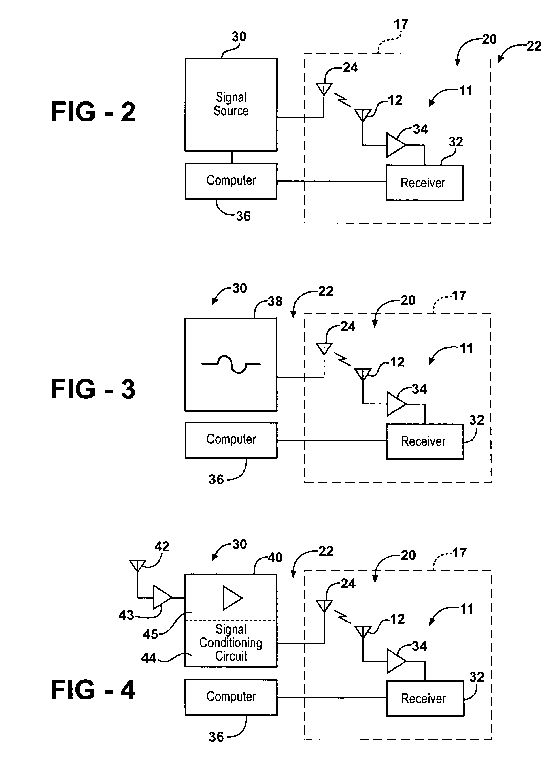
[0030]In a first embodiment, as shown in FIG. 3, the signal source 30 is implemented as a signal generator 38. As such, the signal generator 38 is in communication with the transmitting antenna 24. The signal generator 38 produces a waveform that is used as the RF testing signal. The waveform may be a simple, repetitive sinusoid. Alternatively, the waveform may be modulated by frequency, amplitude, or phase. In addition, the waveform may encode digital data. Those skilled in the art realize numerous other different and modified waveforms that may be generated by the signal generator 38 to be used as the RF testing signal.

second embodiment

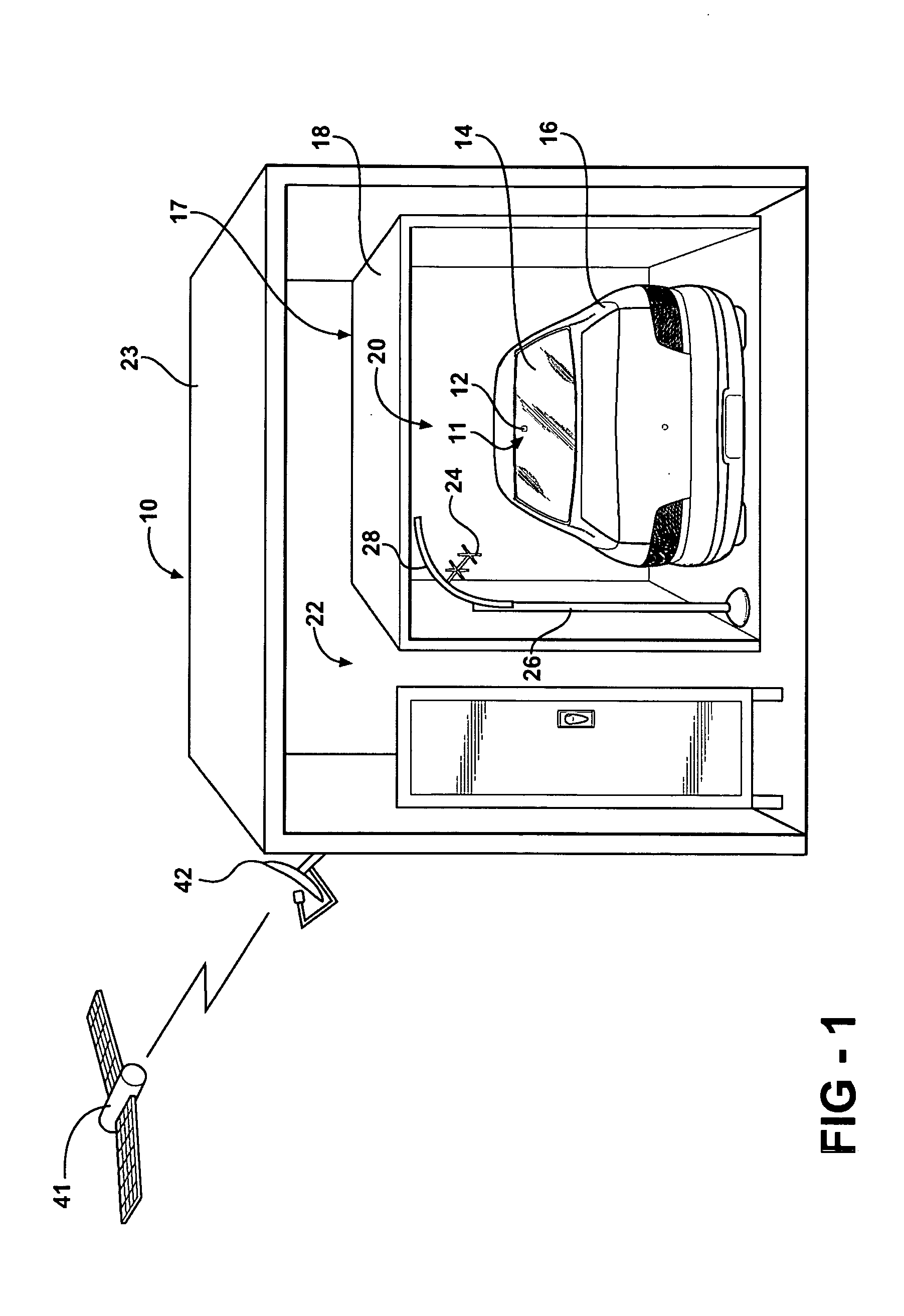
[0031]In a second embodiment, as shown in FIG. 4, the signal source 30 is implemented as a repeater 40 for receiving and retransmitting a signal. As such, the repeater 40 is in communication with the transmitting antenna 24. The repeater is also in communication with an exterior antenna 42. The exterior antenna 42 is disposed outside of the RF testing facility 17 for receiving an RF broadcast signal. That is, the exterior antenna 42 is disposed in the exterior 22 of the RF testing facility 17. When the RF testing facility 17 is implemented as the chamber 18, the RF broadcast signal may be received unencumbered by the RF suppression of the chamber 18.

[0032]In the second embodiment, the RF exterior antenna 42 receives the RF broadcast signal from a satellite 41, such as one of the satellites used by a Satellite Digital Audio Radio Service (SDARS) provider. As such, the RF broadcast signal has a circularly polarized waveform. However, the RF broadcast signal may be broadcast from terre...

third embodiment

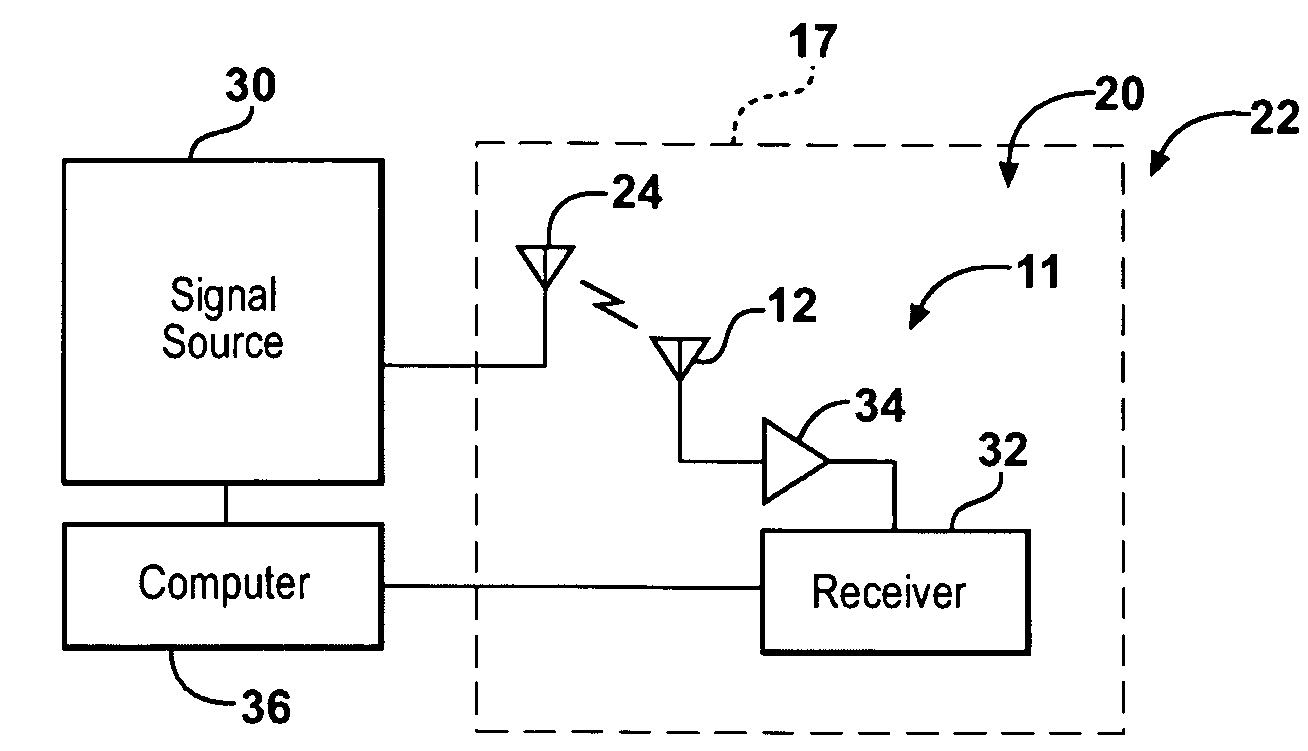
[0042]In a third embodiment, as shown in FIG. 6, the signal source 30 is implemented using both the signal generator 38 and the repeater 40. A switch 54 is electrically connected between the transmitting antenna 24, the signal generator 38, and the repeater 40. This arrangement allows communication of the RF testing signal either between the repeater 40 and the transmitting antenna 24 or between the signal generator 38 and the transmitting antenna 24. The switch 54 is preferably coupled to the computer 36. This allows the computer 36, running an analysis program, to automatically switch between using the signal generator 38 and the repeater 40 as the signal source 30.

[0043]The subject invention also presents a method of testing the subject antenna 12 disposed in the RF anechoic chamber18. The steps of this method have been described above with relationship to the system 10 and are recited hereafter for purposes of convenience. However, although the steps of the method are described ...


PUM


Abstract

A signal measurement system tests an RF component in an RF test facility, such as an RF anechoic chamber. The system includes a repeater which is connected to an exterior antenna disposed outside the chamber and a transmitting antenna disposed inside the chamber. The repeater receives the RF broadcast signal from the exterior antenna and rebroadcasts it as an RF testing signal inside the chamber. The subject antenna receives the RF testing signal, which is then analyzed with a computer. The repeater may also modify the RF testing signal to produce a wide variety of test situations that mimic those available in a traditional field-test.

Description

CROSS REFERENCE TO RELATED APPLICATION[0001]This application claims the benefit of U.S. Provisional Application No. 60 / 944,553, filed Jun. 18, 2007, which is hereby incorporated by reference.BACKGROUND OF THE INVENTION[0002]1. Field of the Invention[0003]The subject invention generally relates to a signal measurement system and method for testing an RF component. More specifically, the subject invention relates to a signal measurement system and method utilizing an RF anechoic chamber.[0004]2. Description of the Related Art[0005]Testing of RF components, such as antennas, receivers, amplifiers, etc., is critical to verify their actual performance either independently or when integrated into a system. Typically, testing of such RF components is performed utilizing RF anechoic chambers and / or field tests in less controlled conditions. These field tests often lead to inaccurate, unreliable, unrepeatable, and inefficient results, since they are subject to several uncontrollable factors....

Claims


Application Information

Patent Timeline
Patent Type & Authority Applications(United States)
IPC IPC(8): G01R29/08
CPCG01R29/0871H04B17/391H04B17/20H04B17/0082
Inventor VILLARROEL, WLADIMIROPETROS, ARGY
Owner AGC AUTOMOTIVE AMERICAS CO A DIV OF AGC FLAT GLASS NORTH AMERICA INC
Why Eureka
Try Eureka