
Cursor control method applied to presentation system and computer readable storage medium

Active Publication Date: 2008-12-18
QUANTA COMPUTER INC
View PDF17 Cites 11 Cited by
  • Summary
  • Abstract
  • Description
  • Claims
  • Application Information

AI Technical Summary

Benefits of technology

[0011]Because the invention moves the internal cursor displayed by the computer based on the distance between the internal cursor and the external cursor within the captured image, even if the camera lens is seriously twisted or the point of view is inaccurate, the invention can still provide good compensation. In other words, even though the projector or the camera is shifted a little, the cursor can still be controlled precisely by the invention.

Problems solved by technology

However, the projected or captured image 16 has to be re-calibrated once one of the following happens: the projector 12 or the camera 14 is shifted, the camera lens is seriously twisted, or the point of view is inaccurate.
Because the '214 patent utilizes linear interpolation for calibration, it cannot compensate lens for non-linear inaccuracy.

Method used


Image

  • Cursor control method applied to presentation system and computer readable storage medium
  • Cursor control method applied to presentation system and computer readable storage medium
  • Cursor control method applied to presentation system and computer readable storage medium

Examples


Embodiment Construction

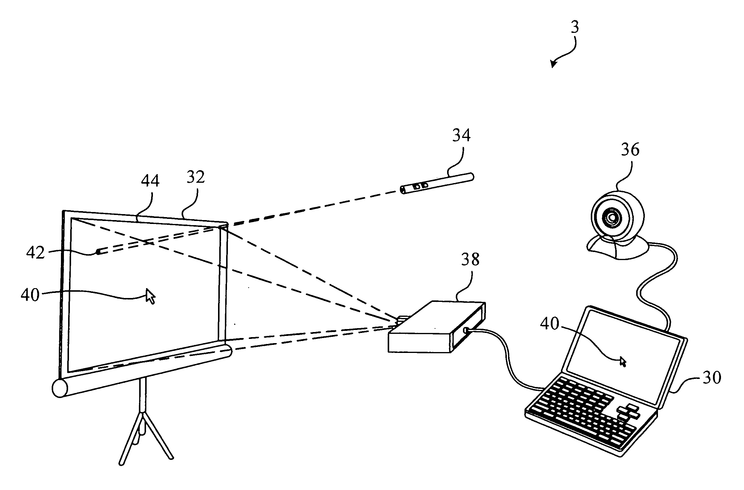
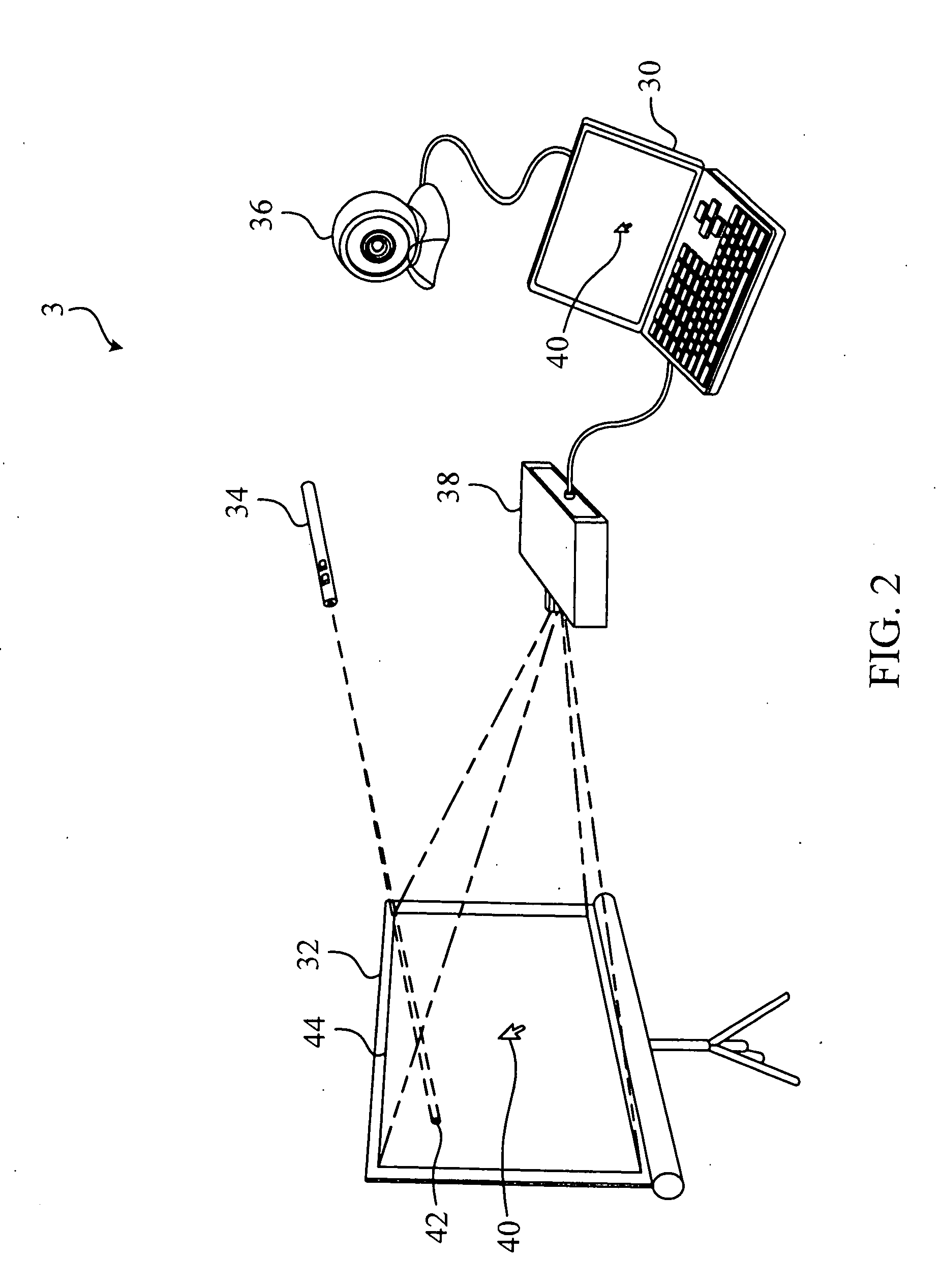
[0018]Please refer to FIG. 2 and FIG. 3. FIG. 2 is a schematic diagram illustrating a presentation system 3 according to a preferred embodiment of the invention. FIG. 3 is a schematic diagram illustrating a shift vector {right arrow over (P2P1)}, between an internal cursor 40 and an external cursor 42.

[0019]A presentation system 3 comprises a computer 30, an imaging plane 32, an optical pointer 34, a camera 36, and a projector 38. The camera 36 and the projector 38 could be mobile or built-in the computer 30, such as a web camera. The camera 36 and the projector 38 can also be integrated into the computer 30 or an electronic device associated with the computer 30. In this embodiment, the camera 36 and the projector 38 are mobile ones associated with the computer 30, as depicted in FIG. 2.

[0020]The imaging plane 32 is associated with the computer 30 for displaying an output of the computer 30, wherein the output of the computer 30 comprises an internal cursor 40 generated by the comp...


PUM


Abstract

The invention discloses a cursor control method applied to a presentation system. The presentation system comprises a computer, an imaging plane, an optical pointer, a camera, and a projector. The projector is a mobile or built-in projector of the computer for projecting output from the computer onto the imaging plane, wherein the output of the computer comprises an internal cursor generated by the computer. The optical pointer is used for projecting an external cursor onto the imaging plane. The camera is a mobile or built-in camera of the computer for capturing an image of the imaging plane. After capturing the image, a processor of the computer detects both a first position of the external cursor and a second position of the internal cursor corresponding to the image, calculates a shift vector between the first and second positions, and moves the internal cursor based on the shift vector.

Description

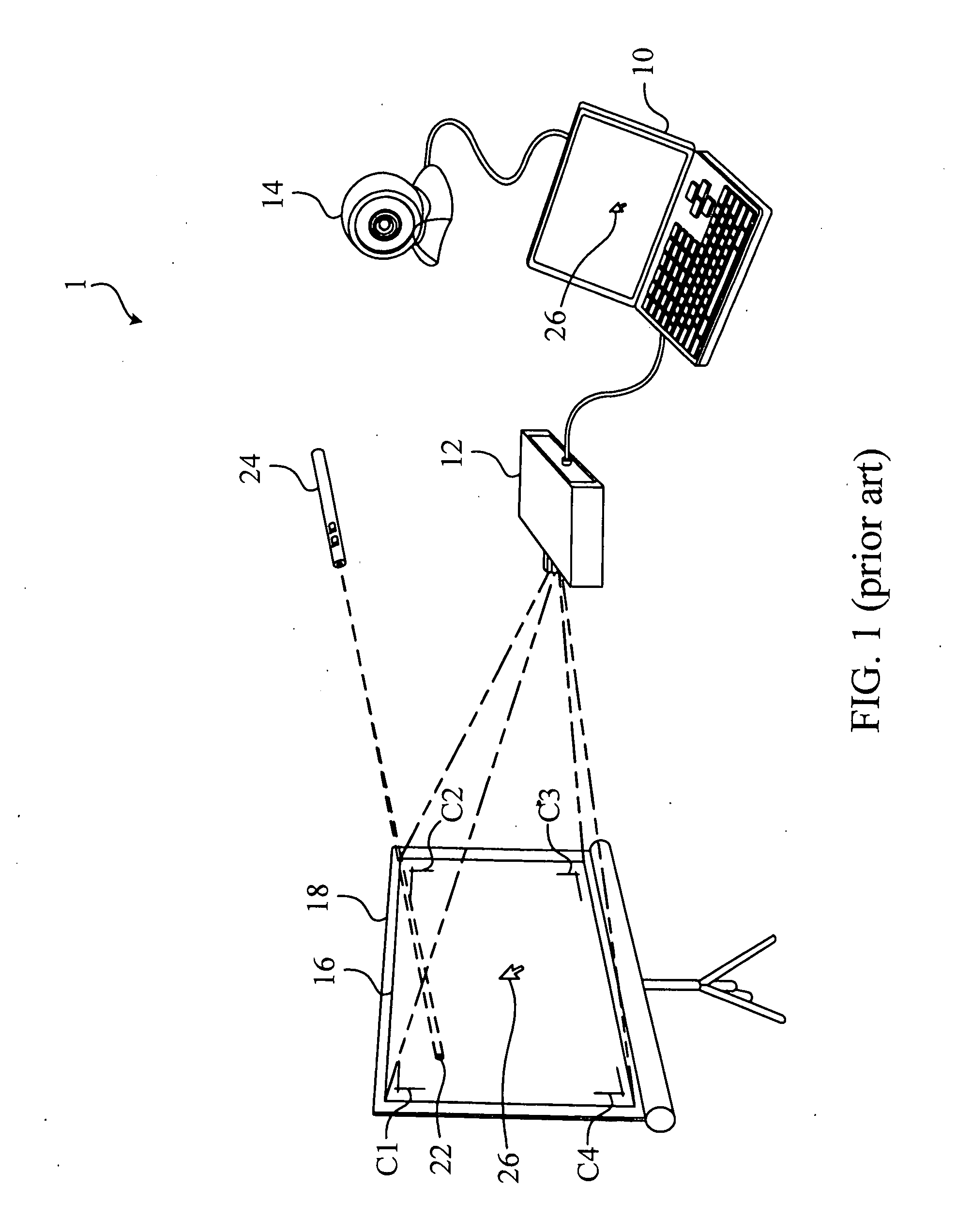
BACKGROUND OF THE INVENTION[0001]1. Field of the Invention[0002]The invention relates to a method and system for remotely controlling a cursor generated by a computer by utilizing an optical pointer.[0003]2. Description of the Prior Art[0004]In recent years, the method and system for remotely controlling a computer has been developed, such as invention disclosed in U.S. Pat. No. 6,275,214 (hereinafter '214 patent). Please refer to FIG. 1. FIG. 1 is a schematic diagram illustrating a presentation system 1 of the '214 patent.[0005]As depicted in FIG. 1, a computer 10 is respectively connected to a projector 12 and a camera 14. The projector 12 projects an image 16 outputted from the computer 10 onto an imaging plane 18, such as a screen. An optical pointer 24 projects an external cursor 22 onto the imaging plane 18. The camera 14 captures the image 16 and the external cursor 22 on the imaging plane 18. Afterward, the captured image 16 and the external cursor 22 are processed by the co...

Claims


Application Information

Patent Timeline
IPC IPC(8): G06F3/033G06F3/038
CPCG06F3/03542G06F3/0386
Inventor LEUNG, CHEE-CHUNLIU, YUN-CHENGCHIANG, CHING-CHUNHSU, MAW-LIN
Owner QUANTA COMPUTER INC
Learn More