Imaging system, image sensor, and method of controlling imaging system

a technology of image sensor and imaging system, which is applied in the field of imaging system, image sensor, and method of controlling imaging system, can solve the problems of short period from the start to the completion of the reset operation, and may not be able to adequately reset the charges accumulated in pixels, so as to reduce the generation of image lag

Inactive Publication Date: 2008-12-18
CANON KK
View PDF13 Cites 6 Cited by
  • Summary
  • Abstract
  • Description
  • Claims
  • Application Information

AI Technical Summary

Benefits of technology

[0012]The present invention provides an imaging system capable of reducing generation of an ima

Problems solved by technology

As a result, the period from the start to completion of the reset operation becomes short.
In this case, charges a

Method used


Image

  • Imaging system, image sensor, and method of controlling imaging system
  • Imaging system, image sensor, and method of controlling imaging system
  • Imaging system, image sensor, and method of controlling imaging system

Examples


second embodiment

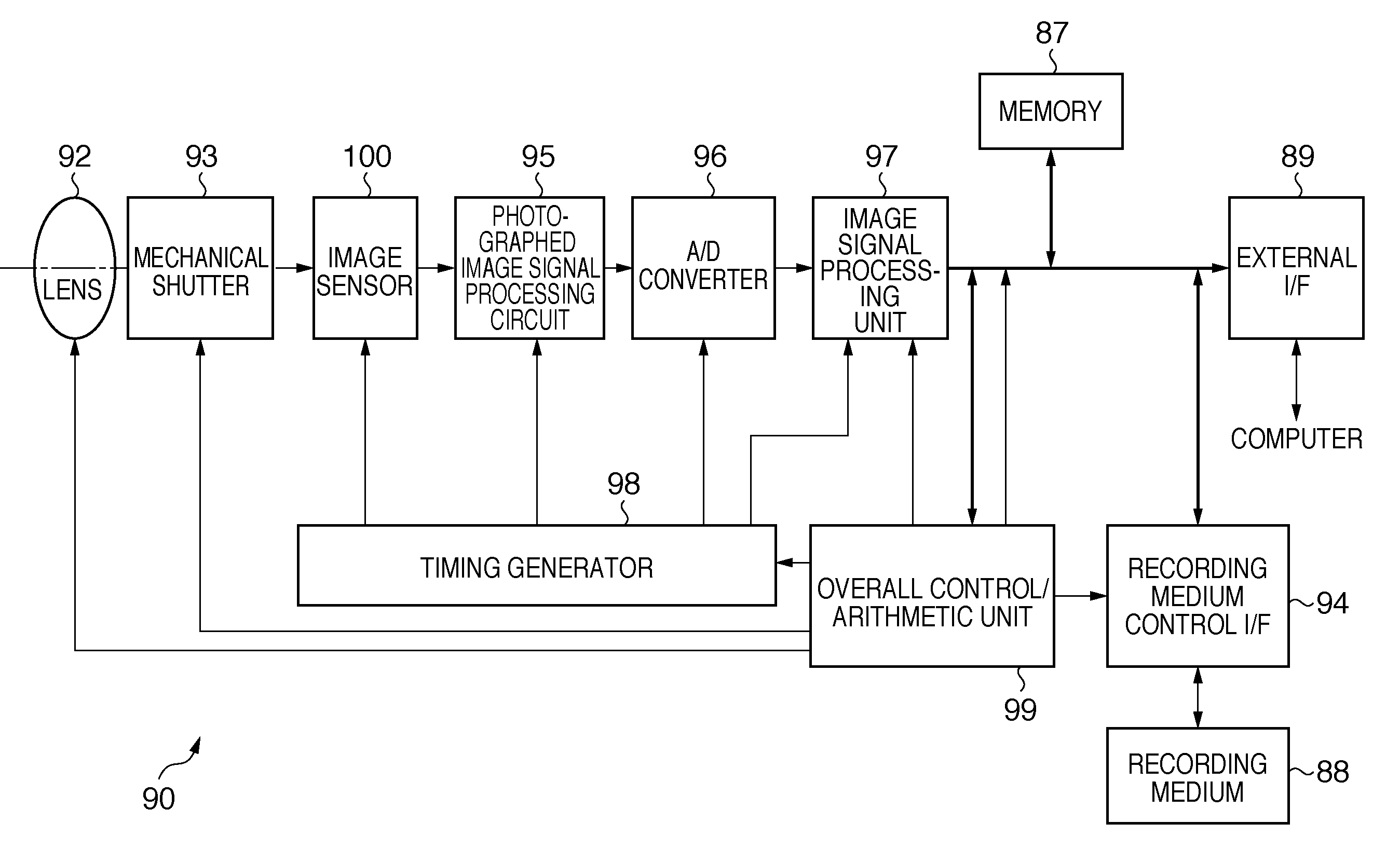
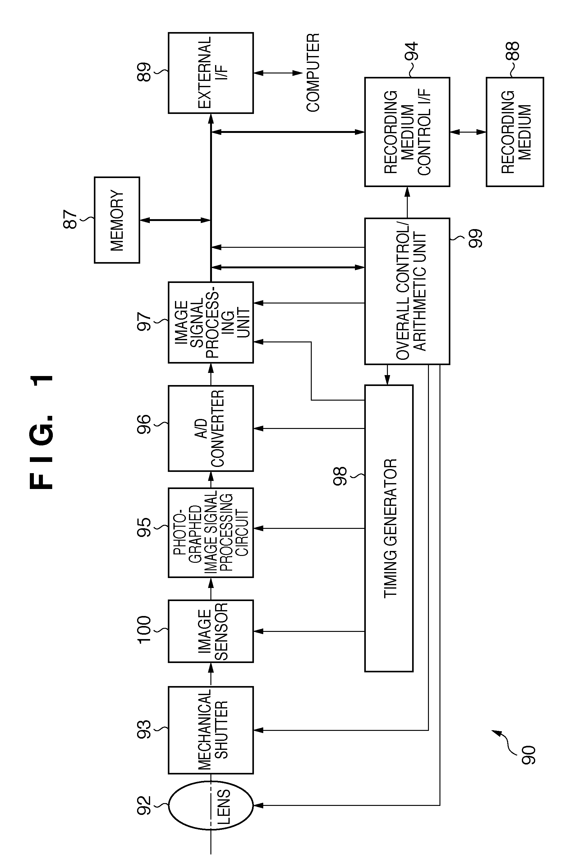
[0097]An imaging system 490 according to the present invention will be described with reference to FIGS. 8 and 9. FIG. 8 is a circuit diagram showing the circuit configuration of an image sensor 400. FIG. 9 is a view showing the operation timings of pixels on the respective rows of a pixel array PA of the image sensor 400.

[0098]The image sensor 400 of the imaging system 490 has the same basic arrangement as that in the first embodiment, but is different from the first embodiment in that the image sensor 400 comprises a vertical scanning unit 420.

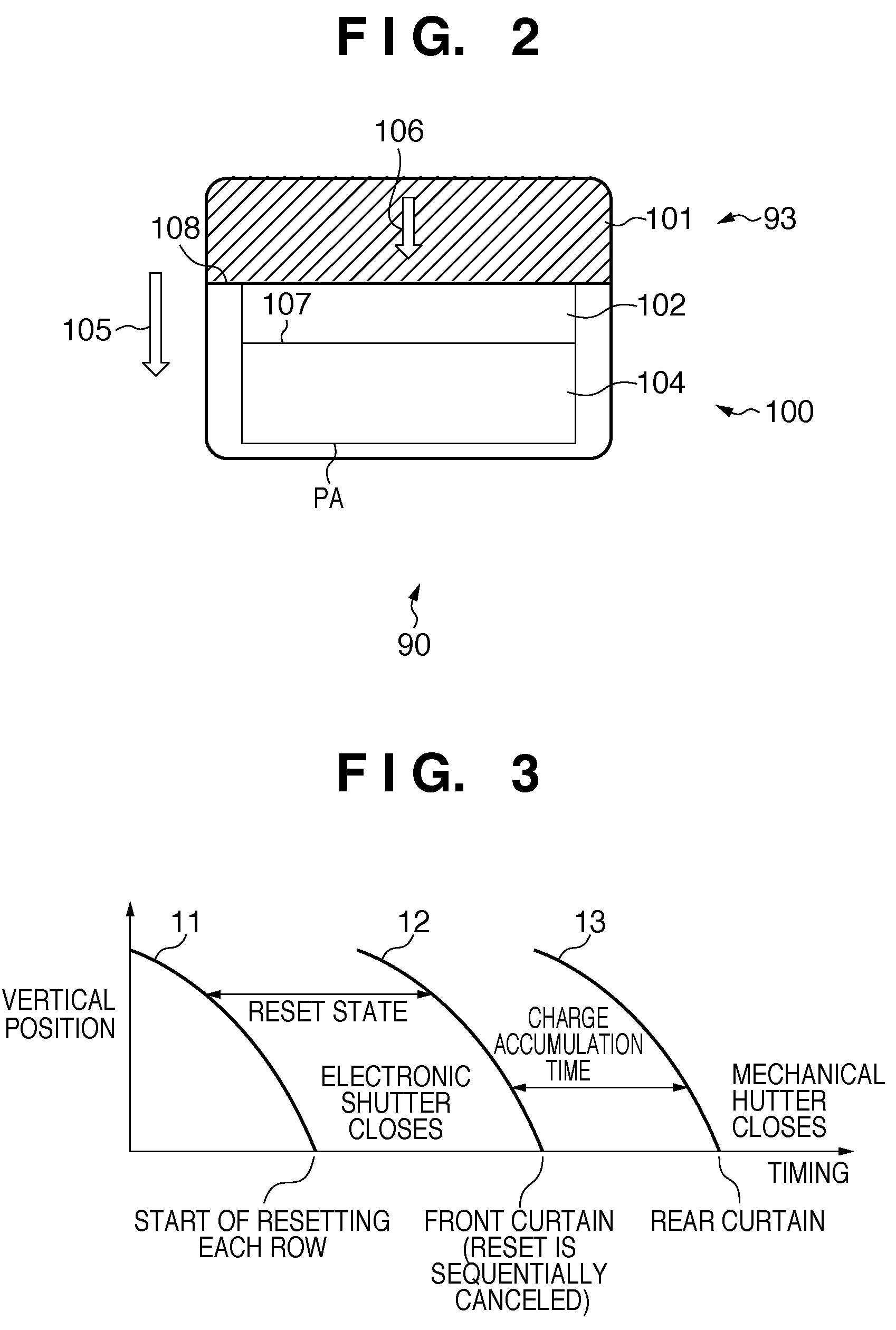
[0099]As shown in FIG. 9, the vertical scanning unit 420 parallelly executes part of the reset operations of pixels on at least two adjacent rows. The vertical scanning unit 420 makes the period until the reset operation is completed after the reset operation starts longer on a row on which the passage speed of a leading edge 108 (see FIG. 2) of a mechanical rear curtain 101 is low than on a row on which the passage time of the leading edge ...

third embodiment

[0103]An imaging system 590 according to the present invention will be described with reference to FIGS. 10 and 11. FIG. 10 is a circuit diagram showing the circuit configuration of an image sensor 500. FIG. 11 is a view showing the operation timings of pixels on the respective rows of a pixel array PA of the image sensor 500.

[0104]The image sensor 500 of the imaging system 590 has the same basic arrangement as that in the first embodiment, but is different from the first embodiment in that a vertical scanning unit 520 includes a first vertical scanning unit 520a and second vertical scanning unit 520b.

[0105]The first vertical scanning unit 520a executes reset start scanning at once for the pixels of the pixel array PA. The second vertical scanning unit 520b executes reset completion scanning sequentially for the pixels of the pixel array PA. That is, the vertical scanning unit 520 starts at once the reset operations of pixels on at least two adjacent rows (see a straight line 11b i...

fourth embodiment

[0113]An imaging system 690 according to the present invention will be described with reference to FIGS. 15 to 17. FIG. 15 is a view showing the layout of an image sensor 600 and mechanical shutter 93. FIG. 16 is a circuit diagram showing the circuit configuration of the image sensor 600. FIG. 17 is a view showing the operation timings of pixels on the respective rows of a pixel array PA of the image sensor 600.


PUM


Abstract

An imaging system includes an image sensor and a mechanical shutter which controls the termination of exposure of the image sensor. The image sensor includes a pixel array in which a plurality of pixels are arrayed in a matrix, and a vertical scanning unit which scans the pixel array for each row. The vertical scanning unit parallelly executes some of the reset operations of pixels on at least two adjacent rows of the pixel array. The charge accumulation operation of pixels starts upon completion of the reset operation and terminates in response to light shielding by the mechanical shutter.

Description

BACKGROUND OF THE INVENTION[0001]1. Field of the Invention[0002]The present invention relates to an imaging system, an image sensor, and a method of controlling the imaging system.[0003]2. Description of the Related Art[0004]An imaging system such as a digital camera sometimes uses an image sensor including a pixel array in which a plurality of pixels are arrayed in a matrix, as shown in FIG. 25. The following technique is proposed to control the charge accumulation operation of pixels on each row of the pixel array.[0005]As a general technique, the start of the charge accumulation operation of pixels on each row of the pixel array is controlled by the pixel reset operation, and the completion of the charge accumulation operation is controlled by the read operation of signals from pixels.[0006]As another technique, the start of the charge accumulation operation of pixels on each row is controlled by the pixel reset operation, and the completion of the charge accumulation operation i...

Claims


Application Information

Patent Timeline
IPC IPC(8): H04N5/335H04N5/235H04N5/353H04N5/357H04N5/374H04N5/376
CPCH04N5/3532H04N5/3745H04N25/531H04N25/77
Inventor ARISHIMA, YUUHIYAMA, HIROKI
Owner CANON KK
Why Eureka
Try Eureka