Defect imaging apparatus, defect detection system having the same, and method of detecting defects using the same

a defect imaging and defect detection technology, applied in the direction of image data processing, semiconductor/solid-state device testing/measurement, instruments, etc., can solve the problem of reducing the efficiency of the semiconductor device manufacturing process, requiring longer time for correction of equipment errors, and requiring more time for generating imaging errors. , to achieve the effect of facilitating detection, reducing time and cost of generating imaging errors, and increasing the accuracy of imaging errors

Inactive Publication Date: 2017-11-28
SAMSUNG ELECTRONICS CO LTD
View PDF12 Cites 0 Cited by
  • Summary
  • Abstract
  • Description
  • Claims
  • Application Information

AI Technical Summary

Benefits of technology

[0033]According to an example embodiment of the present inventive concepts, the reference defect RD may be intentionally provided on the reference area of the substrate W with a sufficient size for facilitating the detection. The actual position of the reference defect RD obtained by the detection may be compared the conversion position of the same reference defect RD, thereby generating the imaging error of the defect imaging apparatus, which may reduce the time and cost for generating the imaging error and may increase the accuracy of the imaging error.
[0034]For example, when a plurality of the inspection apparatuses and a plurality of the defect imaging apparatuses may be combined in a single defect detection system, the imaging error of the defect imaging apparatus may vary according to the pair of the inspection apparatus and the defect imaging apparatus. In such a case, the time and cost for the detection of the actual positions of a plurality of the reference defects and the generation of the imaging error of each pair of the apparatuses may be significantly reduced regardless of how many pairs of the inspection apparatus and the defect imaging apparatus are provided in the defect detection system.
[0035]Further, the automatic detection of the actual positions of the reference defect and the generation of the imaging error may facilitate the statistical treatment to a plurality of differences between a plurality of actual positions and a plurality of conversion positions of a plurality of the reference defects, thereby rapidly generating a more accurate imaging error.

Problems solved by technology

However, the manual detection of the central position of the reference defect usually takes relatively long time, which results in considerable efficiency reduction of the manufacturing process for semiconductor devices.
Further, recent technical trends towards a smaller size and a finer pattern in semiconductor devices make it more challenging to find a reference defect having a size appropriate for the manual search.
Therefore, correction of the equipment errors and coordinate conversion between the inspection apparatus and the defect imaging apparatus take longer times.
For example, when a number of the inspection apparatuses and a number of the defect imaging apparatuses are desired for an efficiency of the defect detection, a setup time for the imaging error correction and coordinate conversion may considerably increase, thereby significantly reducing manufacturing efficiency of the semiconductor devices.
The actual position of the reference defect RD obtained by the detection may be compared the conversion position of the same reference defect RD, thereby generating the imaging error of the defect imaging apparatus, which may reduce the time and cost for generating the imaging error and may increase the accuracy of the imaging error.
Further, the automatic detection of the actual positions of the reference defect and the generation of the imaging error may facilitate the statistical treatment to a plurality of differences between a plurality of actual positions and a plurality of conversion positions of a plurality of the reference defects, thereby rapidly generating a more accurate imaging error.

Method used


Image

  • Defect imaging apparatus, defect detection system having the same, and method of detecting defects using the same
  • Defect imaging apparatus, defect detection system having the same, and method of detecting defects using the same
  • Defect imaging apparatus, defect detection system having the same, and method of detecting defects using the same

Examples


Embodiment Construction

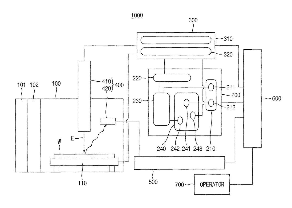
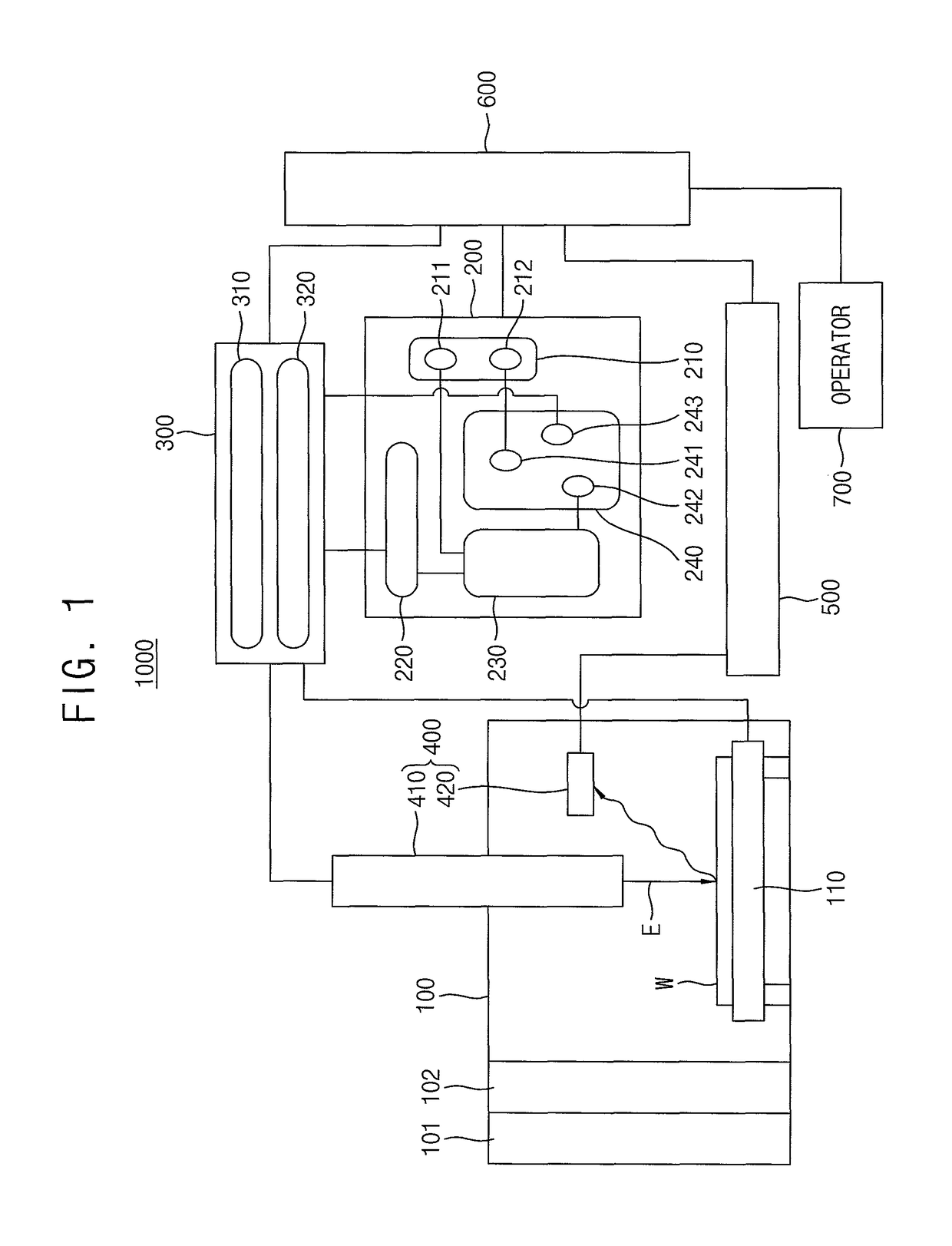
[0051]Various example embodiments will now be described more fully with reference to the accompanying drawings. Example embodiments, however, may be embodied in many different forms and should not be construed as being limited to the example embodiments set forth herein. Rather, these example embodiments are provided so that this disclosure will be thorough and complete, and will fully convey the scope of the inventive concepts to those skilled in the art. In the drawings, the thicknesses of layers and regions may be exaggerated for clarity.

[0052]It will be understood that when an element is referred to as being “on,”“connected to,”“electrically connected to,” or “coupled to” to another component, it may be directly on, connected to, electrically connected to, or coupled to the other component or intervening components may be present. In contrast, when a component is referred to as being “directly on,”“directly connected to,”“directly electrically connected to,” or “directly coupled...


PUM

PropertyMeasurementUnit
sizeaaaaaaaaaa
sizeaaaaaaaaaa
sizeaaaaaaaaaa

Abstract

The defect imaging apparatus including a chamber having a stage to which a substrate having at least one process defect and at least one reference defects defined at a given area is secured, a position controller configured to obtain an imaging error from a detected actual position and a conversion position of the reference defect and correct a conversion position of the process defect by the imaging error, and generate an irradiation position corresponding to an actual position of the process defect, an image signal generator configured to generate an image signal of the process defect by irradiating an electron beam to the irradiation position and detecting charged particles from the irradiation position in response to the irradiated electron beam, and an imaging device configured to generate a defect image of the process defect by processing the generated image signal may be provided.

Description

CROSS-REFERENCE TO RELATED APPLICATIONS[0001]This application claims priority under 35 U.S.C §119 to Korean Patent Application No. 10-2015-0130129 filed on Sep. 15, 2015 in the Korean Intellectual Property Office, the contents of which are incorporated by reference herein in its entirety.BACKGROUND[0002]1. Field[0003]Example embodiments relate to defect imaging apparatuses for imaging defects, defect detection systems having the same, and / or methods of inspecting defects using the same.[0004]2. Description of the Related Art[0005]Defect positions on a semiconductor substrate such as a water are detected by an optical inspection apparatus and defect images corresponding to the defect positions are obtained by a defect imaging apparatus. The defect image usually shows the shape and characteristics of the corresponding defect. Thus, the operator may identify defects on the wafer based on the defect image.[0006]To obtain accurate defect images, the beam irradiator of the defect imaging ...

Claims


Application Information

Patent Timeline
Patent Type & Authority Patents(United States)
IPC IPC(8): G06T7/00H01L21/66G01N21/95
CPCG01N21/9501H01L22/12G01N21/8851G01N2021/8861G01N2021/8867
Inventor PARK, IL-SUKCHO, HYUNG-SUK
Owner SAMSUNG ELECTRONICS CO LTD
Why Eureka
Try Eureka