Storage device

a storage device and a technology for storing devices, applied in the field of storage devices, can solve the problems of affecting the structure of the top cover does not allow the simultaneous fitting of both hook portions, and the difficulty of fitting the hook portion little by little while bending the hook portion as described above, so as to achieve the effect of improving the workability of the member

Inactive Publication Date: 2008-12-18
KK TOSHIBA
View PDF19 Cites 7 Cited by
  • Summary
  • Abstract
  • Description
  • Claims
  • Application Information

AI Technical Summary

Benefits of technology

[0013]It is an object of the present invention to provide a storage device realizing higher assembling workability of a member covering internal components from an outer side.

Problems solved by technology

However, in this device, a work of fitting the hook portions of the bottom cover to the side portions of the upper surface of the top cover is relatively difficult.
Concretely, in the assembling work of the bottom cover, its structure does not allow the simultaneous fitting of the both hook portions.
This work of fitting the hook portion little by little while bending the hook portion as described above is relatively difficult, and improvement is hoped for regarding this problem.
However, simply selecting a soft material results in decreased rigidity of the hook portions themselves.
As a result, the work of gradually fitting the other hook portion from the longitudinal end portion side to the other end portion side becomes difficult.
However, this device still has a problem to be solved regarding assembling workability of the components.

Method used


Image

  • Storage device
  • Storage device
  • Storage device

Examples


example

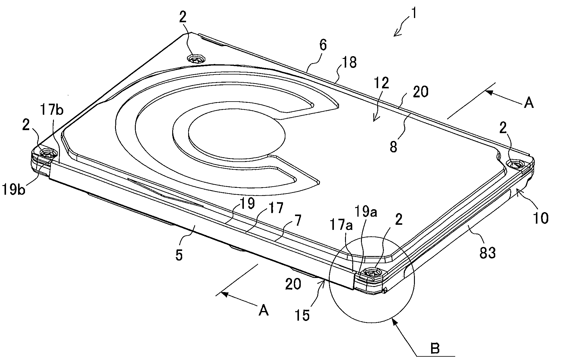
[0057]Next, the present invention will be described based on an example by using FIG. 10 to FIG. 12. Here, FIG. 10 is a plane view of a bottom cover 15 of the example included in the magnetic disk device 1 shown in FIG. 1. FIG. 11 is a plane view of bottom covers 25, 35 of comparative examples 1, 2 compared with the bottom cover 15 in FIG. 10. FIG. 12 is a table showing comparison results of the bottom covers shown in FIG. 10 and FIG. 11 respectively.

[0058]Here, dimensions shown in FIG. 10 and FIG. 11 are as follows: a=71 mm, b=51 mm, c, h, j=4 mm, d=29 mm, e, g=40 mm, f=23 mm, s=33 mm, p=diameter 23 mm, and r=diameter 19 mm. Therefore, in the bottom covers 25, 35 of a circular hole type of the comparative examples 1, 2, an area of an opening portion composed of hole portions 25a, 25b is 23.8% of an area of the whole outer surface. On the other hand, in the bottom cover 15 of a frame type of the example, an area of an opening portion composed of rectangular holes 92, 93 is 71.8% of ...


PUM

PropertyMeasurementUnit
thicknessaaaaaaaaaa
thicknessaaaaaaaaaa
thicknessaaaaaaaaaa

Abstract

A storage device includes: a storage medium including a first and a second main surface; a first cover member disposed on the first main surface side; a second cover member in a frame shape disposed on the second main surface side corresponding to the first cover member; and a pair of hook portions connected to the second cover member and sandwiching outer edge portions of the first cover member.

Description

CROSS-REFERENCE TO RELATED APPLICATIONS[0001]This application is based upon and claims the benefit of priority from the prior Japanese Patent Application No. 2007-160776, filed on Jun. 18, 2007; the entire contents of which are incorporated herein by reference.BACKGROUND OF THE INVENTION[0002]1. Field of the Invention[0003]The present invention relates to a storage device capable of storing information.[0004]2. Description of the Related Art[0005]There has been known a magnetic disk device with a thin structure which can be mounted in a PC (personal computer) card slot owing to a reduction in thickness of its head actuator, voice coil motor, and soon and improvement in layout and the like of such internal components (see, for example, Reference 1 (JP-A 2001-210058 (KOKAI)).[0006]In the device described in the aforesaid document 1, its internal components are covered by a rectangular top cover and a rectangular bottom cover while being sandwiched by these top and bottom covers from a...

Claims


Application Information

Patent Timeline
Patent Type & Authority Applications(United States)
IPC IPC(8): G11B33/02
CPCG11B25/043
Inventor IWASE, TAKAYUKI
Owner KK TOSHIBA
Why Eureka
Try Eureka