
Discharging unit and image forming apparatus having the same

a technology of discharging unit and image forming apparatus, which is applied in the direction of electrographic process apparatus, thin material handling, instruments, etc., can solve the problems of thermal deformation of printing medium, curled printing medium, and jamming of discharging unit, so as to reduce the curling of printing medium

Active Publication Date: 2008-12-18
HEWLETT PACKARD DEV CO LP
View PDF5 Cites 24 Cited by
  • Summary
  • Abstract
  • Description
  • Claims
  • Application Information

AI Technical Summary

Benefits of technology

[0009]Accordingly, it is an aspect of the present invention to provide a discharging unit capable of accommodating the different thicknesses of the printing medium, and capable of reducing the curling of the printing medium, and an image forming apparatus having the same.

Problems solved by technology

During this process, the printing medium may become thermally deformed in the direction of the heat being applied, and may become curled as a result.
The printing medium when so curled may interfere, and / or be interfered with, printing medium previously discharged, and may push the already discharged printing medium out of alignment from a neat stack, and may even become jammed within the discharging unit.
Although the rectilinear property could be enhanced by the crossing roller disclosed, however, unfortunately, the disclosed structure, since the pair of elastic rollers reciprocally rotate with a predetermined nip, cannot accommodate different thicknesses of the various types of printing medium.

Method used


Image

  • Discharging unit and image forming apparatus having the same
  • Discharging unit and image forming apparatus having the same
  • Discharging unit and image forming apparatus having the same

Examples


Embodiment Construction

[0028]Reference will now be made in detail to the embodiments of the present invention, examples of which are illustrated in the accompanying drawings, wherein like reference numerals refer to like elements throughout.

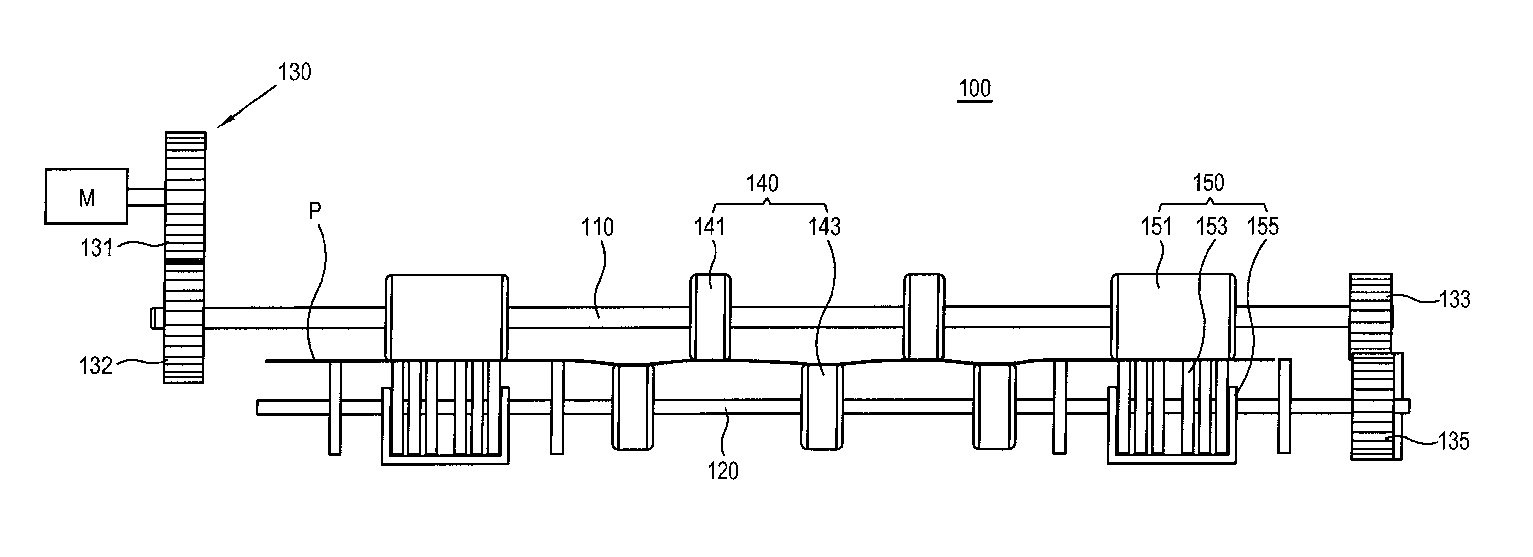
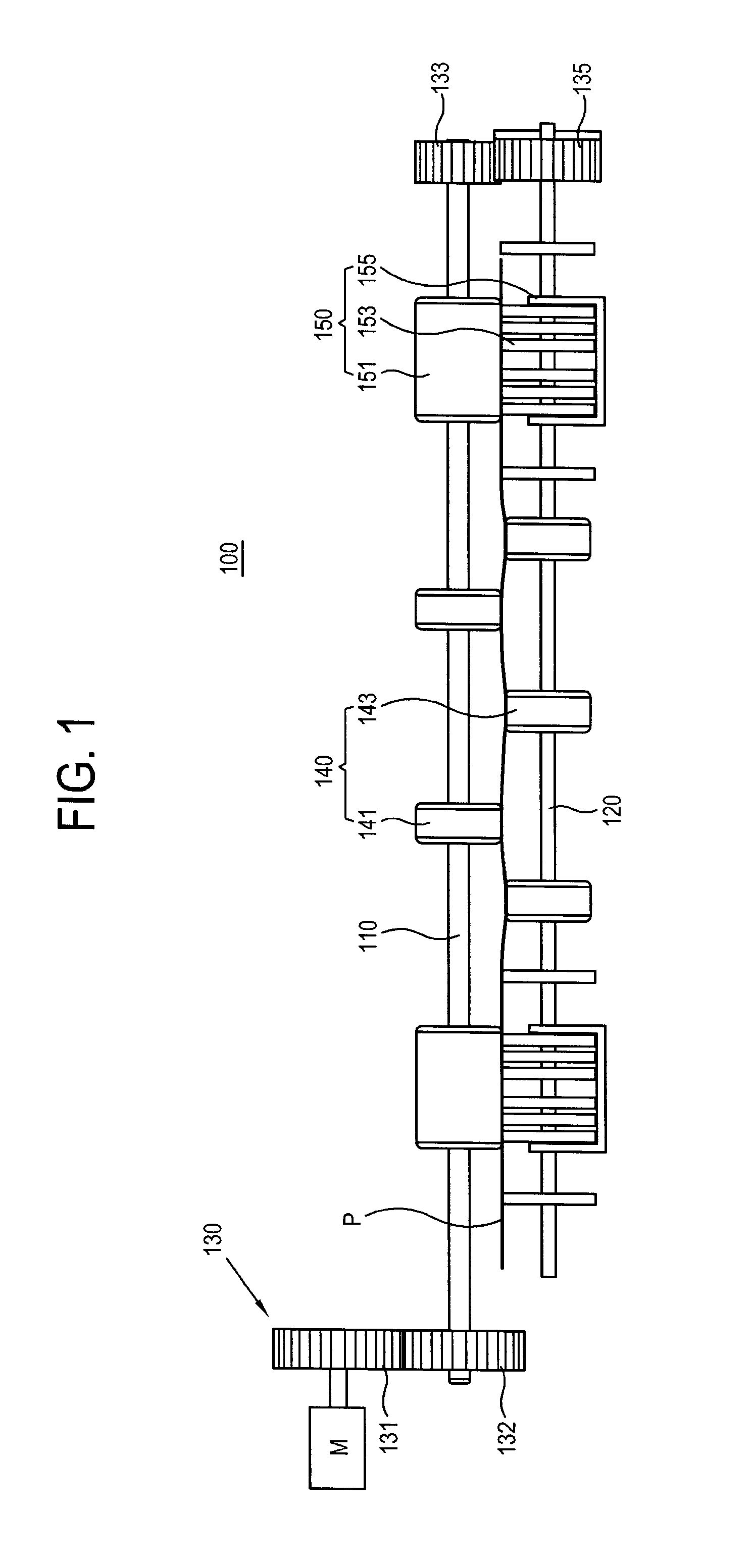
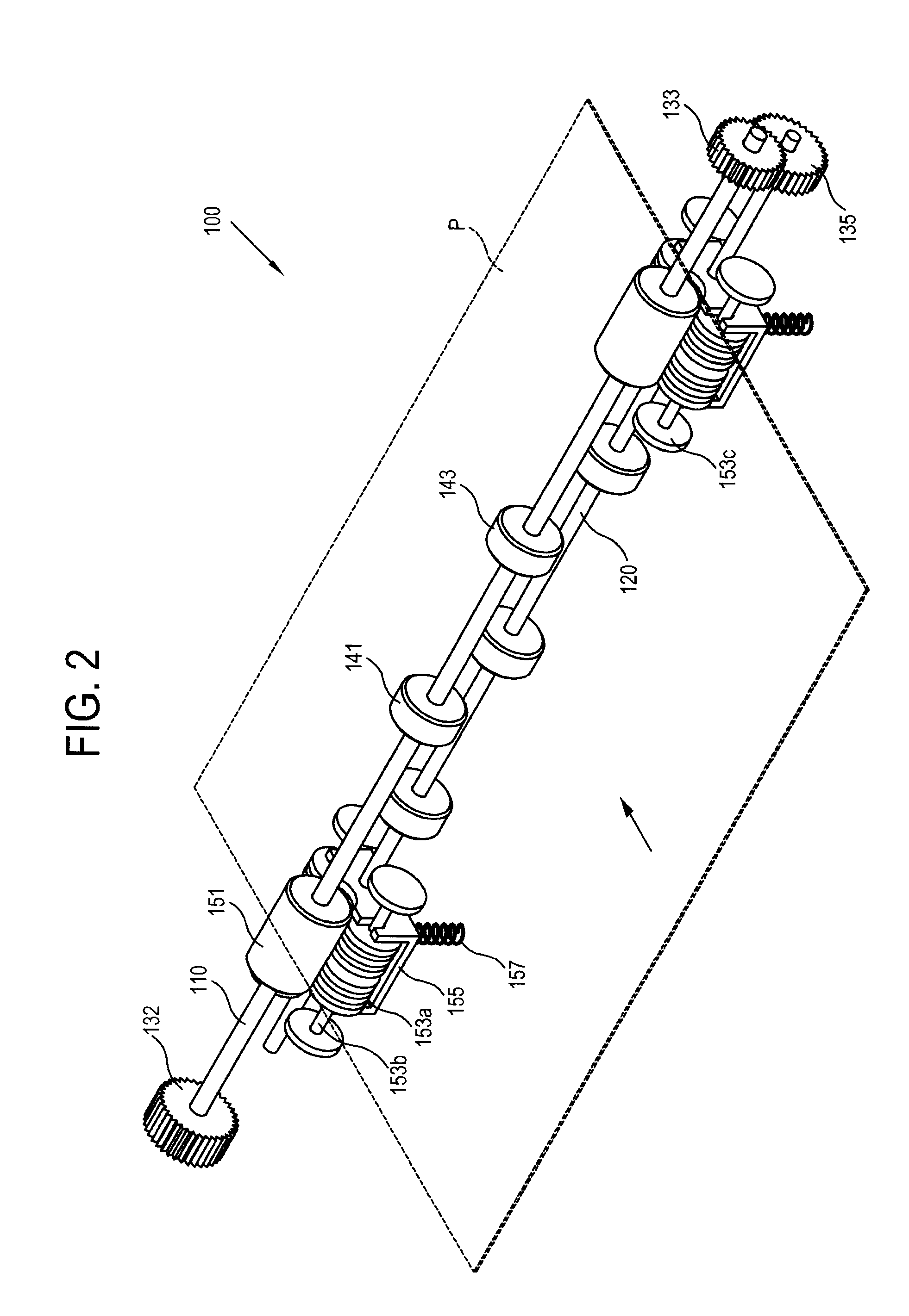
[0029]FIG. 1 and FIG. 2 are a front view and a perspective view illustrating a configuration of a discharging unit according to an exemplary embodiment of the present invention. As shown in FIGS. 1 and 2, the discharging unit 100 according to the present invention includes a first rotational shaft 110 and a second rotational shaft 120 which are provided to be parallel with each other, a power transmission unit 130 which transmits power to the first rotational shaft 110 and the second rotational shaft 120, a crossing roller unit 140 for enhancing the rectilinear property of a printing medium P, and a curl preventing roller unit 150 which is provided to elastically move to adjust to the thickness of the printing medium P to reduce the curling of the printing medium.

[0030...


PUM


Abstract

A discharging unit for discharging a printing medium from an image forming apparatus includes an elastic roller and a curl preventing roller to oppose each other in a pressing relationship forming a nip therebetween to reduce curling of a print medium passing through the nip. At least one of the elastic roller and the curl preventing roller is allowed to move towards or away from the other roller so that the nip can be adjusted to accommodate different thicknesses of varying types of printing medium.

Description

CROSS-REFERENCE TO RELATED APPLICATIONS[0001]This application claims priority from Korean Patent Application No. 10-2007-0057474, filed on Jun. 12, 2007 in the Korean Intellectual Property Office, the disclosure of which is incorporated herein by reference.BACKGROUND OF INVENTION[0002]1. Field of Invention[0003]Apparatuses and methods consistent with the present invention relate to a discharging unit and an image forming apparatus having the same, and more particularly, to a discharging unit capable of reducing the curling, and enhancing the rectilinear property, of a printing medium, and to an image forming apparatus having the same.[0004]2. Description of the Related Art[0005]A discharging unit may discharge various printing media such as, e.g., a standard printing paper, wallpaper, transparencies, glossy photograph paper, or the like, from an image forming apparatus, which forms a visual recording such as a pattern, text, an image on the surface of the printing medium, and may th...

Claims


Application Information

Patent Timeline
Patent Type & Authority Applications(United States)
IPC IPC(8): G03G15/00
CPCG03G15/6552G03G15/6576G03G2215/00421G03G2215/00662B41J11/00B41J13/00
Inventor LEE, CHOONG-YONG
Owner HEWLETT PACKARD DEV CO LP
Learn More