Dental Impression Trays

a technology for dental impressions and trays, which is applied in the field of dental impression trays, can solve the problems of increasing the time consumption and dental model production costs of dental models, inconvenient use of conventional ready-made dental impression tray sets, and inconvenient adjustment for operators, etc., and achieves the effects of convenient use, quick extraction of dental impressions, and efficient us

Inactive Publication Date: 2008-12-18
OROBIOTECH
View PDF8 Cites 13 Cited by
  • Summary
  • Abstract
  • Description
  • Claims
  • Application Information

AI Technical Summary

Benefits of technology

[0024]The present invention can adjust the width of the dental impression tray to match the sizes of patient's dental arches which are different from each other by the dental cavity and teeth of a patient, so that the tray can be adapted to all of the patients. Furthermore, the adjusted width of the tray can be stably maintained during the procedure of obtaining an impression of teeth of a patient, so that a correct dental impression can be quickly obtained.
[0025]Furthermore, the dental impression tray of the present invention is manufactured as a disposable tray using an inexpensive synthetic resin material. Thus, this dental impression tray can be discarded without requiring sterilization and disinfection after being used, thereby being convenient to the operators and allowing the operators to execute dental operations under healthy conditions. Furthermore, the tray has implant holes, thus being efficiently used during an implanting operation. Therefore, this dental impression tray can be used as a multipurpose impression tray.

Problems solved by technology

Thus, the conventional ready-made dental impression tray set is inconvenient to use.
Therefore, it is necessary to readjust the rotated container parts 111 to the correct shape, but the readjustment is very inconvenient to an operator.
This increases the time consumption and dental model production costs.
But, the metal trays force the owners of the trays to pay excessive money because the owners must purchase many trays which are classified by size into large-sized, middle-sized and small-sized trays.
However, because the sterilization and disinfection of the metal trays must be executed for a lengthy period of time, some operators of the trays may quickly sterilize the trays, thus making the trays unhealthy and unsanitary.
Thus, the trays are inevitably contaminated with saliva of the patient during the procedure of determination of the dental arch size of the patient, so that, even if all of the trays are sterilized and disinfected after being used in the determination of the dental arch size of the patient, the work to obtain the impression of teeth of a subsequent patient may be executed under unhealthy conditions.
However, it is difficult to completely remove the impression material from the dental impression tray, so that the tray may be reused with remnants of the previously used impression material stuck to the tray, thus creating unsanitary and unhealthy conditions.

Method used


Image

  • Dental Impression Trays
  • Dental Impression Trays
  • Dental Impression Trays

Examples


first embodiment

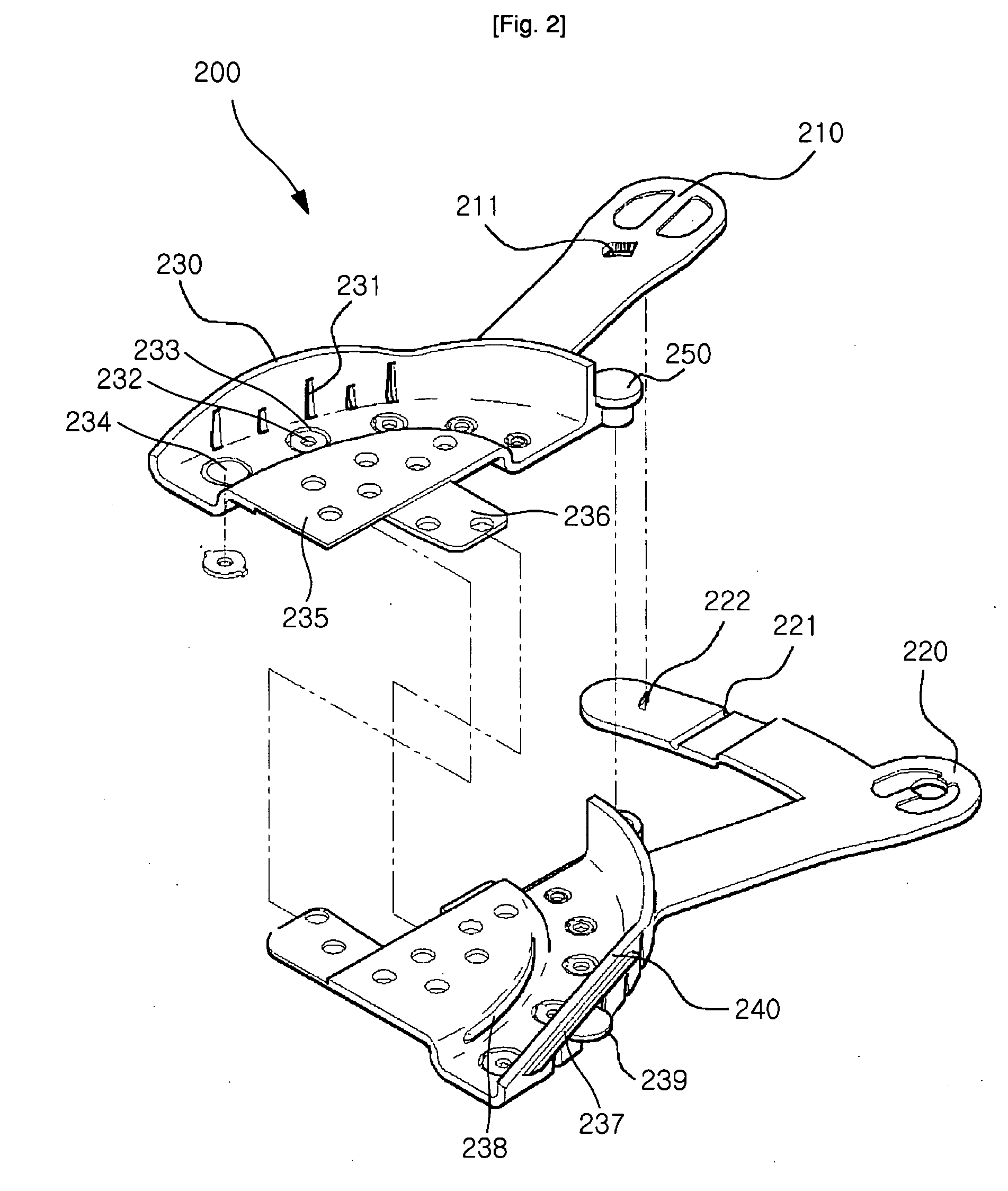
[0038]FIG. 2 is an exploded perspective view illustrating a maxillary impression tray according to the present invention. FIG. 3 is a perspective view illustrating the assembled maxillary impression tray of FIG. 2. FIGS. 4 and 5 are perspective views illustrating the operation of the maxillary impression tray of FIG. 3.

[0039]As shown in FIGS. 2 through 5, the dental impression tray 200 according to the first embodiment of the present invention comprises first and second handles 210 and 220 to be gripped and handled by an operator, first and second impression material container parts 230 and 240 to contain an impression material therein, and a pivot part 250 to pivot the two container parts 230 and 240 together so that the two container parts 230 and 240 can be rotated around the pivot part 250 by manipulating the handles 210 and 220.

[0040]The first and second impression material container parts 230 and 240 are separated from each other, and the first container part 230 is integrated...

second embodiment

[0051]FIG. 6 is an exploded perspective view illustrating a maxillary impression tray according to the present invention. FIG. 7 is a perspective view illustrating the assembled maxillary impression tray of FIG. 6.

[0052]As shown in FIGS. 6 and 7, the dental impression tray according to the second embodiment is constructed such that, although the width between the first and second impression material container parts 230 and 240 is adjusted and increased, the engaging parts 235a engage and overlap with each other over a maximum area, so that the first and second container parts 230 and 240 securely engage with each other. Described in detail, the two engaging parts 235a provided in the dental impression tray according to this embodiment have the same shape. However, the overlapping parts of the two engaging parts 235a, at which the two engaging parts 235a overlap with each other, are thinner than the other parts and have respective seats on the upper and lower surfaces thereof. The se...

third embodiment

[0053]FIG. 8 is an exploded perspective view illustrating a maxillary impression tray according to the present invention. FIG. 9 is a perspective view illustrating the assembled maxillary impression tray of FIG. 8.

[0054]As shown in FIGS. 8 and 9, the dental impression tray according to the third embodiment is constructed such that the tray can be particularly adapted to a patient having wisdom teeth or having an uncommonly big dental arch. Therefore, the general shape of the dental impression tray according to the third embodiment remains the same as that described for the embodiment shown in FIG. 3, but the size of the first and second impression material container parts 230 and 240 is increased. Described in detail, each of the first and second container parts 230 and 240 has both a first locking hole 261, which is formed around the end of each container part 230, 240, and a second locking hole 262 which is formed around an implant hole 232 provided at the end of each container pa...


PUM


Abstract

Disclosed is a dental impression tray realized such that the width of the dental impression tray can be adjusted to match different sizes of patient's dental arches and the adjusted width of the dental impression tray can be stably maintained during the procedure of obtaining an impression of teeth of a patient. The dental impression tray includes first and second container parts to contain an impression material therein, the container parts being shaped to correspond to a patient's dental arch and being separated from each other; a pivot part to pivot the first and second container parts together such that the container parts can be rotated around the pivot part, thus adjusting the width between the container parts; and a handle part extending from the container parts and being gripped and handled by an operator while adjusting the width between the container parts, and being provided with a locking means for stably locking the first and second container parts in positions corresponding to an adjusted width. Thus, the present invention can adjust the width of the dental impression tray to match sizes of patient's dental arches which are different from each other by the dental cavity and teeth of a patient, so that the tray can be adapted to all of the patients. Furthermore, the adjusted width of the tray can be stably maintained during the procedure of obtaining an impression of teeth of a patient, so that a correct dental impression can be quickly obtained.

Description

BACKGROUND OF THE INVENTION[0001]1. Technical Field[0002]The present invention relates, in general, to dental impression trays and, more particularly, to a dental impression tray which is realized such that the width of the dental impression tray can be adjusted to match different sizes of patient's dental arches and the adjusted width of the dental impression tray can be stably maintained during the procedure of obtaining an impression of teeth of a patient.[0003]2. Background Art[0004]Dental impression trays are dental instruments that are used for obtaining impressions of teeth of a patient using impression materials when it is required to make a dental model by copying the shape of a patient's oral cavity so as to examine and treat a defect or damage to teeth of the patient.[0005]To obtain a correct impression of patient's teeth, it is required to select a correct dental impression tray after determining the horseshoe-shaped dental arch of the selected dental impression tray, wh...

Claims


Application Information

Patent Timeline
Patent Type & Authority Applications(United States)
IPC IPC(8): A61C9/00
CPCA61C9/0006
Inventor KIM, KI-SUKLEE, JUN-HEE
Owner OROBIOTECH
Why Eureka
Try Eureka