Transceiver

a transceiver and receiver technology, applied in the field of transceivers, can solve the problems of carrier leakage, difficult filter realization, and large physical size of the off-chip, and achieve the effect of reducing interference and reducing interferen

Active Publication Date: 2008-12-18
RENESAS ELECTRONICS CORP
View PDF2 Cites 94 Cited by
  • Summary
  • Abstract
  • Description
  • Claims
  • Application Information

AI Technical Summary

Benefits of technology

This patent describes how to decrease interference caused by signals transmitted through wireless networks. By controlling the frequencies used for transmission and reducing errors during synchronization, this technology can improve the quality of these signals and minimize interference between them.

Problems solved by technology

This patent discusses various techniques related to improving the performance of wireless transceivers. However, these solutions face issues like carrier leakage and difficulty in realizing them in practical applications. The technical problem addressed in this patent is how to effectively implement a direct up-conversion architecture without compromising accuracy and reliability while reducing costs and complexity.

Method used


Image

  • Transceiver
  • Transceiver
  • Transceiver

Examples


Embodiment Construction

1. Summary of the Preferred Embodiments

[0059]First, the preferred embodiments of the invention herein disclosed will be presented in outline. In the description here, the reference numerals, characters or signs to refer to the drawings, which are accompanied with paired round brackets, only exemplify what the concepts of components referred to by the numerals, characters or signs contain.

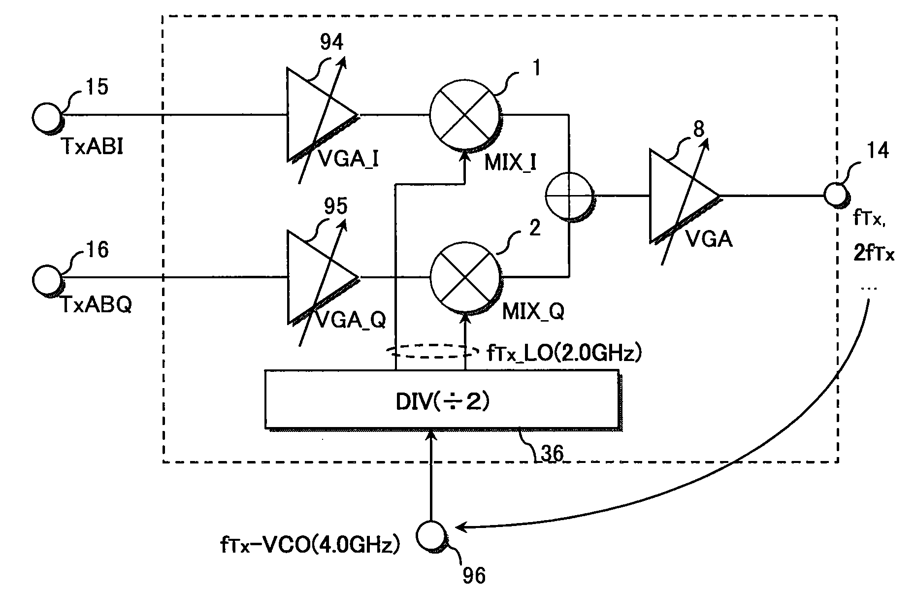
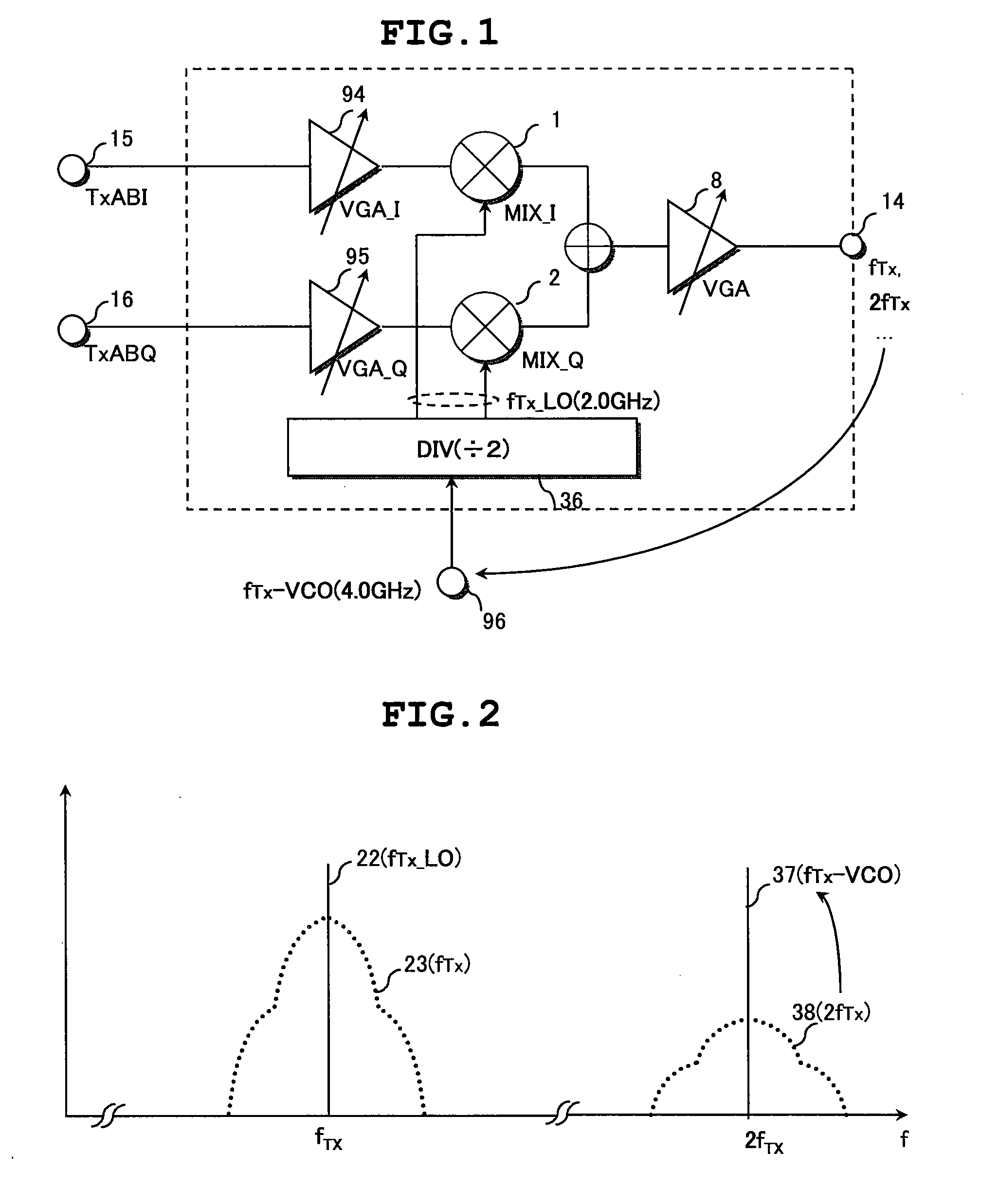
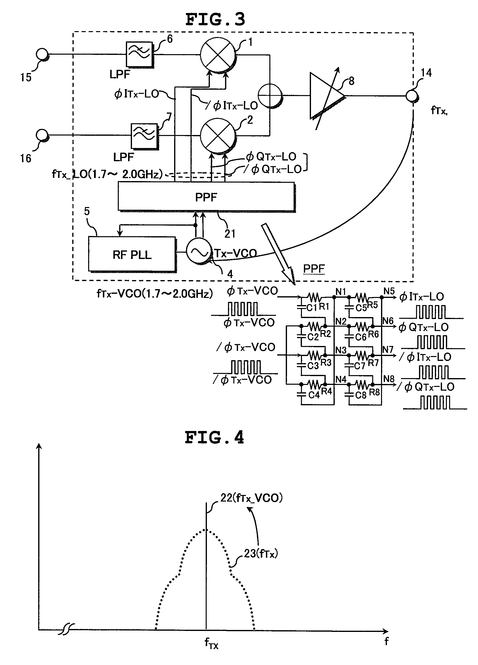
[0060][1] A transceiver according to a preferred embodiment of the invention has a receiver including a receiver-side demodulator for converting a received RF receive signal into an analog receive signal, and a transmitter including a transmitter-side modulator for converting an analog transmit signal into an RF transmit signal.

[0061]The transmitter further includes a digital-to-analog converter (9,10) for converting a digital transmit signal (I, Q) into the analog transmit signal (I′, Q′). The transmitter further includes: a transmitter-side voltage-controlled oscillator (4); and a transmitter-side...


PUM


Abstract

The transmitter of the transceiver includes: a transmitter-side mixers of a transmitter-side modulator; a transmitter-side voltage-controlled oscillator; and a transmitter-side divider. The divider having a dividing factor of a non-integral number is supplied with an oscillating output of the oscillator. A pair of non-quadrature local signals having a phase difference of 90° plus a predetermined offset angle is produced by the divider and supplied to the mixers. The transmitter includes a phase-shift unit which converts a pair of quadrature transmit signals having a phase difference of about 90° on an analog basis into a pair of non-quadrature shifted transmit signals. Consequently, quadrature modulation is performed by the mixers. Use of a similar configuration enables the reduction in interference of an RF signal with local signals supplied to receiver-side mixers of the receiver.

Description


Claims


Application Information

Patent Timeline
Owner RENESAS ELECTRONICS CORP
Why Eureka
Try Eureka