Test method and apparatus for spark plug insulator
a technology of spark plugs and test methods, which is applied in the direction of spark plugs, material breakdown voltage, instruments, etc., can solve the problems of increased equipment cost, deterioration of productivity, and labor-intensive pressure control operation, so as to improve accuracy, improve productivity, and improve cost
- Summary
- Abstract
- Description
- Claims
- Application Information
AI Technical Summary
Benefits of technology
Problems solved by technology
Method used
Image
Examples
first embodiment
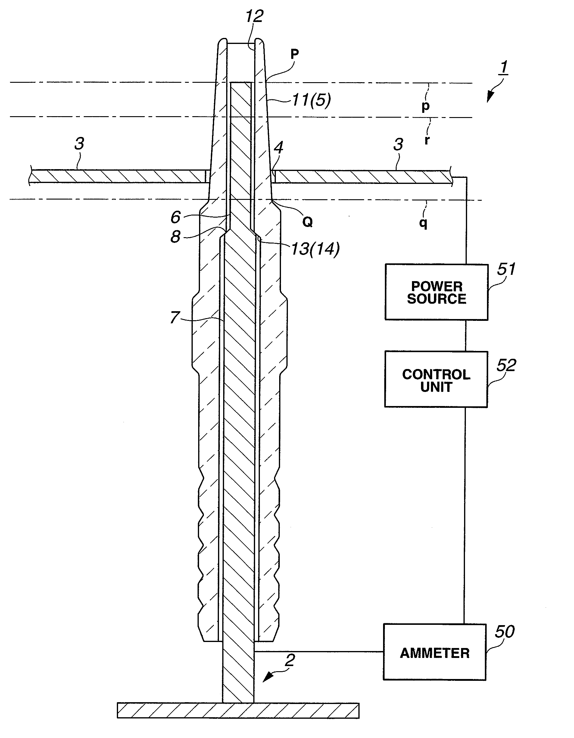
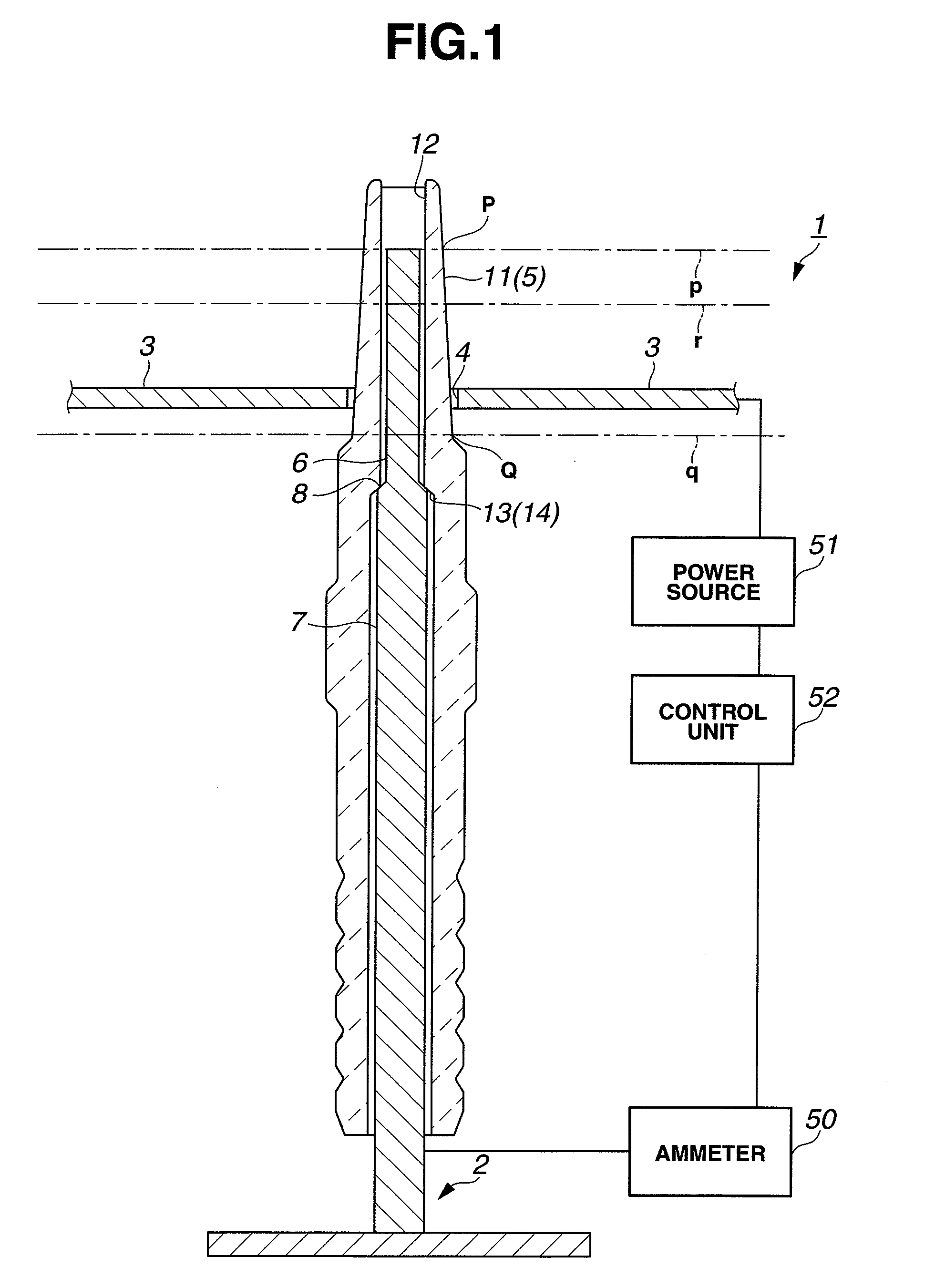
[0024]The first embodiment refers to a method for testing the presence or absence of a defect in a ceramic insulator 11 by a test apparatus 1. The ceramic insulator 11 is designed, for use in a spark plug, as a cylindrical molded sintered piece of a ceramic material e.g. alumina with an axial through hole 12 as shown in FIG. 1. A stepped surface 13 is formed on the axial through hole 12 of the ceramic insulator 11 so as to retain thereon a center electrode of the spark plug. In the first embodiment, the ceramic insulator 11 has a shape that varies in thickness in the axial direction thereof and defines a contour part of the spark plug. (Hereinafter, the ceramic insulator 11 as the test sample may occasionally be referred to as the sample insulator.)
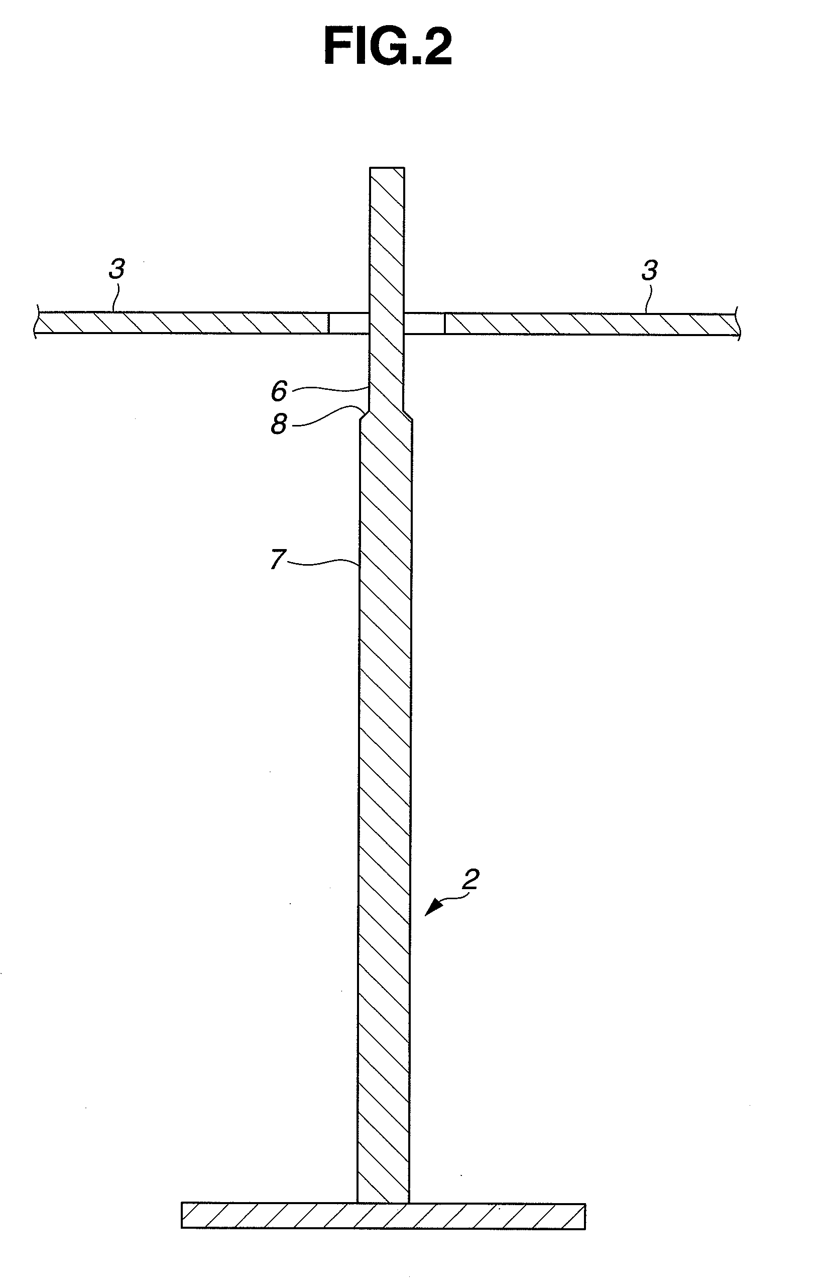
[0025]As shown in FIGS. 1 and 2, the test apparatus 1 includes a first test electrode 2, a second test electrode 3, a reference insulator 5, an ammeter 50, a direct-current power source 51 and a control unit 52.
[0026]The first test electr...
second embodiment
[0050]The second embodiment is similar to the first embodiment, except that a test apparatus 101 of the second embodiment is capable of simultaneous defect detection tests on a plurality of ceramic insulators 11 at a plurality of points. For simplification purposes, one ceramic insulator 11 is illustrated in FIGS. 5 and 6. Although the test apparatus 101 has an ammeter 50, a direct-current power source 51 and a control unit 52 as in the case of the first embodiment, these structural components 50, 51 and 52 are omitted from FIGS. 5 and 6 for simplification purposes.
[0051]As shown in FIG. 5, the test apparatus 101 includes a net-shaped holder 15 with openings 15a so that the ceramic insulators 11 can be held in the respective openings 15a of the holder 15 and carried at once by movement of the holder 15. The holder 15 is supported by an insulating support member and kept from electrical contact with the ceramic insulators 11 so as not to produce an electrical effect on the ceramic in...
third embodiment
[0064]The third embodiment is similar to the second embodiment, except that a test apparatus 201 of the third embodiment has a different number of second test electrodes and carries out a test voltage determination process in a different manner. In FIG. 8, one ceramic insulator 11 is illustrated for simplification purposes. Although the test apparatus 201 has an ammeter 50, a direct-current power source 51 and a control unit 52 as in the case of the first and second embodiments, these structural components 50, 51 and 52 are omitted from FIG. 8 for simplification purposes.
[0065]As shown in FIG. 8, the test apparatus 201 has three second test electrodes 3a, 3b and 3c: two second test electrodes 3a and 3b on the front side of the holder 15 and one second test electrode 3c on the rear side of the holder 15.
[0066]In the third embodiment, the defect detection test program takes place in the same manner as in the first and second embodiments, except for the test voltage determination proce...
PUM
| Property | Measurement | Unit |
|---|---|---|
| distances | aaaaa | aaaaa |
| short-circuit voltage | aaaaa | aaaaa |
| short-circuit voltage | aaaaa | aaaaa |
Abstract
Description
Claims
Application Information
 - R&D
- Intellectual Property
- Life Sciences
- Materials
- Tech Scout
- Unparalleled Data Quality
- Higher Quality Content
- 60% Fewer Hallucinations
Browse by: Latest US Patents, China's latest patents, Technical Efficacy Thesaurus, Application Domain, Technology Topic, Popular Technical Reports.
© 2025 PatSnap. All rights reserved.Legal|Privacy policy|Modern Slavery Act Transparency Statement|Sitemap|About US| Contact US: help@patsnap.com


