
Outer blade for reciprocation-type electric shaver and method of producing the same

Active Publication Date: 2010-07-01
MATSUSHITA ELECTRIC WORKS LTD
View PDF20 Cites 5 Cited by
  • Summary
  • Abstract
  • Description
  • Claims
  • Application Information

AI Technical Summary

Benefits of technology

[0005]It is an object of the present invention to provide an outer blade for a reciprocation-type electric shaver capable of suppressing a deformation such as wrinkles and an undulation in the outer blade, without adding a component such as the deformation prevention plate, to thereby keep a good appearance, and a method of producing the outer blade.
[0009]In the above outer blade and method of producing the outer blade, the crush of the projection sections included in the deformation suppression section by pressing them from the inside rigidifies lower-end portions of the outer blade to suppress a deformation such as wrinkles and an undulation in the lower-end portions. Besides, the formation of the deformation suppression section has little effect on the shape of the outer surface of the outer blade, which permits an improvement of the appearance of the outer blade. Furthermore, the suppression of the deformation requires no addition of any separate component, thus involving no cost increase due to the addition.

Problems solved by technology

However, the addition of the deformation prevention plate increases material expense of the outer-blade and the number of man-hour for assembly, thereby increasing cost.

Method used


Image

  • Outer blade for reciprocation-type electric shaver and method of producing the same
  • Outer blade for reciprocation-type electric shaver and method of producing the same
  • Outer blade for reciprocation-type electric shaver and method of producing the same

Examples


Embodiment Construction

[0022]The best mode for implementing the present invention will be below described in detail with reference to the drawings.

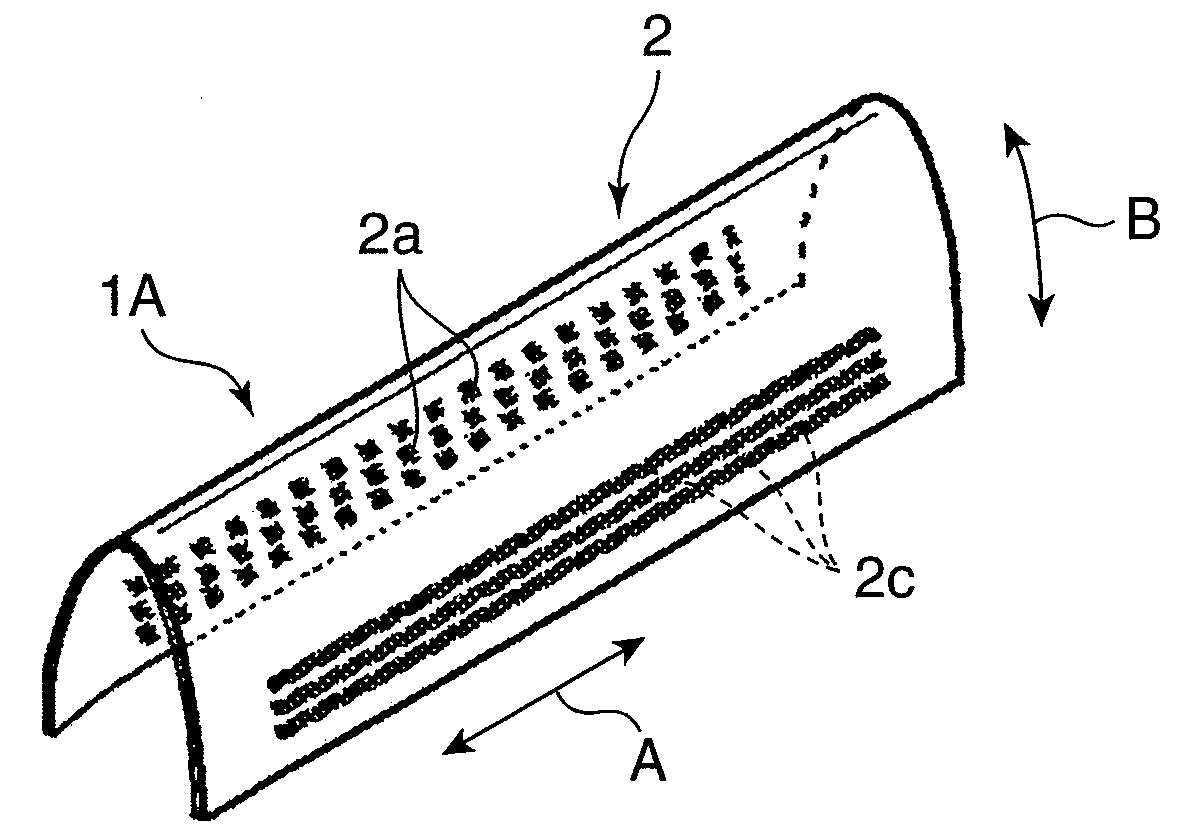
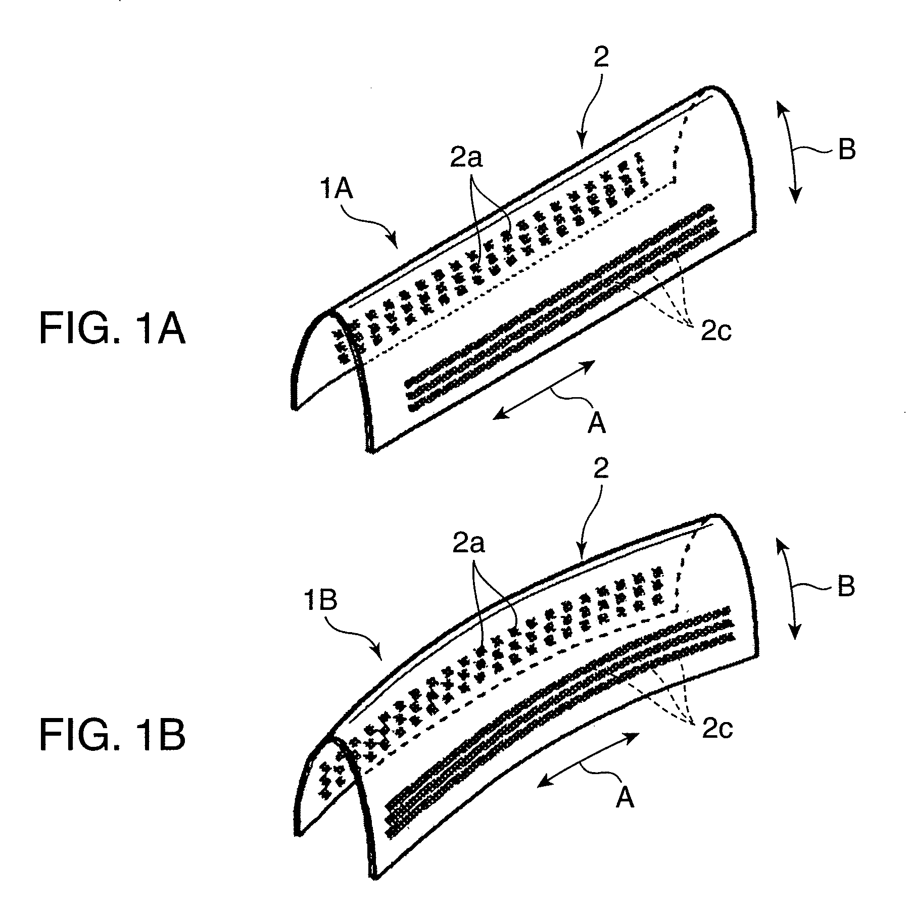
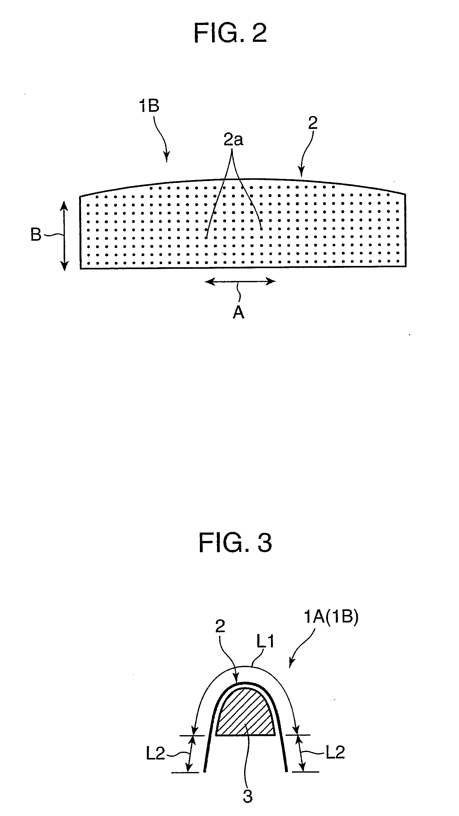
[0023]FIGS. 1A and 1B show outer blades 1A and 1B, respectively, for a reciprocation-type electric shaver according to an embodiment of the present invention. Either of the outer blades 1A and 1B are each formed of a quadrangular sheet material 2 having many hair introduction holes 2a arranged vertically and laterally. The peripheral edge of each hair introduction hole 2a forms, as shown in FIGS. 4 to 6, a projection section 2b embossed inward (upward in FIGS. 4 and 5), in other words, projecting inward beyond the other portion.

[0024]The outer blade 1A of FIG. 1A is formed by bending the sheet material 2 originally shaped like a flat plate shown in FIG. 4 into a reverse-U shape, specifically, in such away that the middle thereof projects upward when viewed in a lateral direction (i.e., in a first direction). On the other hand, the outer blade 1B of FIG. 1B is f...


PUM


Abstract

Provided are an outer blade for a reciprocation-type electric shaver and a method of producing the outer blade, the outer blade being capable of suppressing a deformation such as wrinkles or an undulation, without adding a new component, to thereby keep a good appearance thereof. A sheet material for forming the outer blade is bent into a shape projecting upward when viewed in the lateral directions. The sheet material has hair introduction holes, the peripheral edge of each hair introduction hole forming a projection section projecting inward beyond the other portion of the sheet material, the end surfaces of a part of the projection sections make contact with a reciprocating inner blade. The sheet material is formed with a deformation suppression section in a specific region not including the projection sections which make contact with the inner blade but including the projection sections which make no contact with the inner blade. The deformation suppression section extends in a direction, the projection sections included in the deformation suppression section being crushed by pressing from the inside of the sheet material.

Description

TECHNICAL FIELD[0001]The present invention relates to an outer blade for a reciprocation-type electric shaver and a method of producing the outer blade.BACKGROUND ART[0002]There is conventionally known a reciprocation-type electric shaver which includes an outer blade and an inner blade adapted to laterally reciprocate while sriding on the inner surface of the outer blade. Patent Document 1 shows an outer blade formed of a quadrangular sheet material having a large number of hair introduction holes and bent into a shape projecting upward when viewed in the lateral directions (e.g., reverse-U shape). In the sheet material, the peripheral edge of each hair introduction hole forms a projection section embossed inward (i.e., projecting inward beyond the other portion), and an inner blade reciprocates in contact with the end surface of each projection section to thereby cut a hair inserted through the corresponding hair introduction hole.[0003]The outer blade formed of the quadrangular s...

Claims


Application Information

Patent Timeline
IPC IPC(8): B26B19/02B21K11/00
CPCB26B19/384B26B19/04B26F1/02B26B19/00B30B1/00
Inventor KAWAGUCHI, TATSUJI
Owner MATSUSHITA ELECTRIC WORKS LTD
Learn More