Built-in antenna apparatus and portable terminal having the same

a portable terminal and built-in antenna technology, which is applied in the structural form of the resonant antenna, transmission, radiating element, etc., can solve the problems of affecting the human body, affecting so as to reduce the amount of space needed, improve the performance of the terminal, and increase the slimness of the terminal

Inactive Publication Date: 2009-01-01
SAMSUNG ELECTRONICS CO LTD
View PDF3 Cites 189 Cited by
  • Summary
  • Abstract
  • Description
  • Claims
  • Application Information

AI Technical Summary

Benefits of technology

[0014]Yet another aspect of the present invention is to provide a built-in antenna apparatus configured to realize the same or better radiation characteristics and simultaneously reduce an amount of space needed for installation of an antenna, thus contributing to an improvement in performance of a terminal and an increase in its slimness, and a portable terminal having the same.

Problems solved by technology

However, these types of antennas are vulnerable to damage when the terminals are accidentally dropped and the damage causes a deterioration of portability.
However, the above structure of the antenna apparatus causes a problem since the terminal gets in close contact with the human body when a terminal is in use.
More particularly, a physical distance between the human head and an antenna radiator are relatively short, thereby resulting in an undesirable SAR affecting the human body.
Also, there is a problem of an increasing size of the antenna radiator due to multiple band use which increases the size of terminal and thus going against the trend of slimmer terminals.

Method used


Image

  • Built-in antenna apparatus and portable terminal having the same
  • Built-in antenna apparatus and portable terminal having the same
  • Built-in antenna apparatus and portable terminal having the same

Examples


Embodiment Construction

[0026]The following description with reference to the accompanying drawings is provided to assist in a comprehensive understanding of exemplary embodiments of the invention as defined by the claims and their equivalents. It includes various specific details to assist in that understanding but these are to be regarded as merely exemplary. Accordingly, those of ordinary skill in the art will recognize that various changes and modifications of the embodiments described herein can be made without departing from the scope and spirit of the invention. Also, descriptions of well-known functions and constructions are omitted for clarity and conciseness.

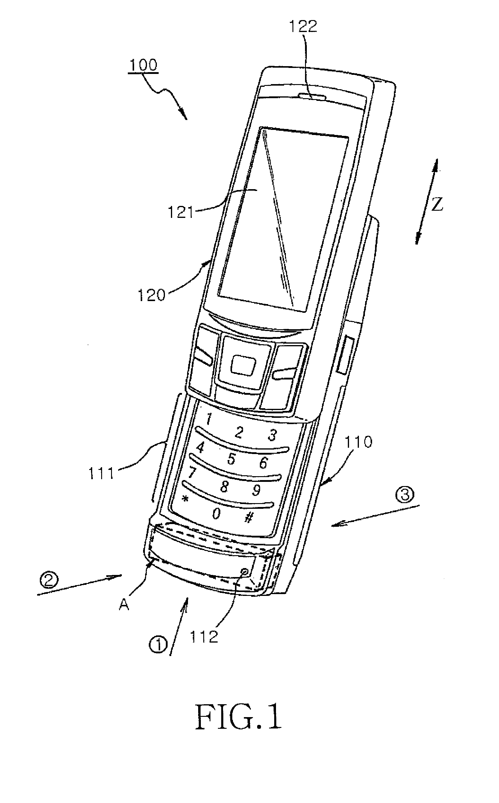
[0027]In the following description of exemplary embodiments of the present invention, a slide type portable terminal is shown and described as an example. However, the present invention is equally applicable to any type of portable terminals that can apply a built-in antenna apparatus.

[0028]FIG. 1 is a perspective diagram illustrating a slide...


PUM


Abstract

A built-in antenna apparatus and a portable terminal including the same are provided. The apparatus includes a substrate, an antenna carrier, a plate type antenna radiator operating in at least one resonance band, and at least one sub antenna radiator. The substrate has a feeding pad for electrically coupling with a Radio Frequency (RF) connector. The antenna carrier for establishing preset distance from the substrate. The plate type antenna radiator is disposed on the antenna carrier. The sub antenna radiator is electrically coupled with the plate type antenna radiator.

Description

PRIORITY[0001]This application claims the benefit under 35 U.S.C. §119(a) of a Korean patent application filed in the Korean Intellectual Property Office on Jun. 27, 2007 and assigned Serial No. 2007-63582, the entire disclosure of which is hereby incorporated by reference.BACKGROUND OF THE INVENTION[0002]1. Field of the Invention[0003]The present invention relates to an antenna apparatus for use with a portable terminal. More particularly, the present invention relates to an antenna apparatus for use with a portable terminal that is configured to maximize its distance from the human head to reduce a Specific Absorption Rate (SAR) while realizing radiation characteristics that are the same or better than radiation characteristics realized with a conventional antenna apparatus, and a portable terminal having the same.[0004]2. Description of the Related Art[0005]In recent years, terminals having a variety of functions and designs have been introduced. While trends in terminal design h...

Claims


Application Information

Patent Timeline
Patent Type & Authority Applications(United States)
IPC IPC(8): H01Q1/24H01Q9/04
CPCH01Q1/38H01Q21/30H01Q9/0421H04B1/38H01Q1/24
Inventor WOO, JIN-SUN
Owner SAMSUNG ELECTRONICS CO LTD
Why Eureka
Try Eureka