Fluid ejecting apparatus and method for controlling the same

a technology of ejecting apparatus and fluid, which is applied in the direction of printing, etc., can solve the problems of clogging of the nozzle with fluid, deteriorating the condition of the channel, printing errors, etc., and achieve the effect of preventing the clogging

Inactive Publication Date: 2009-01-01
SEIKO EPSON CORP
View PDF4 Cites 37 Cited by
  • Summary
  • Abstract
  • Description
  • Claims
  • Application Information

AI Technical Summary

Benefits of technology

[0008]An advantage of some aspects of the invention is that the nozzles are prevented

Problems solved by technology

One problem with such fluid ejecting apparatuses, however, is that the nozzle may become clogged with fluid.
In such instances, the clogs cause troubles such as missing dots during the printing operation, making it necessary to eliminate the fluid causing the clogging.
Furthermore, in the structu

Method used


Image

  • Fluid ejecting apparatus and method for controlling the same
  • Fluid ejecting apparatus and method for controlling the same
  • Fluid ejecting apparatus and method for controlling the same

Examples


second embodiment

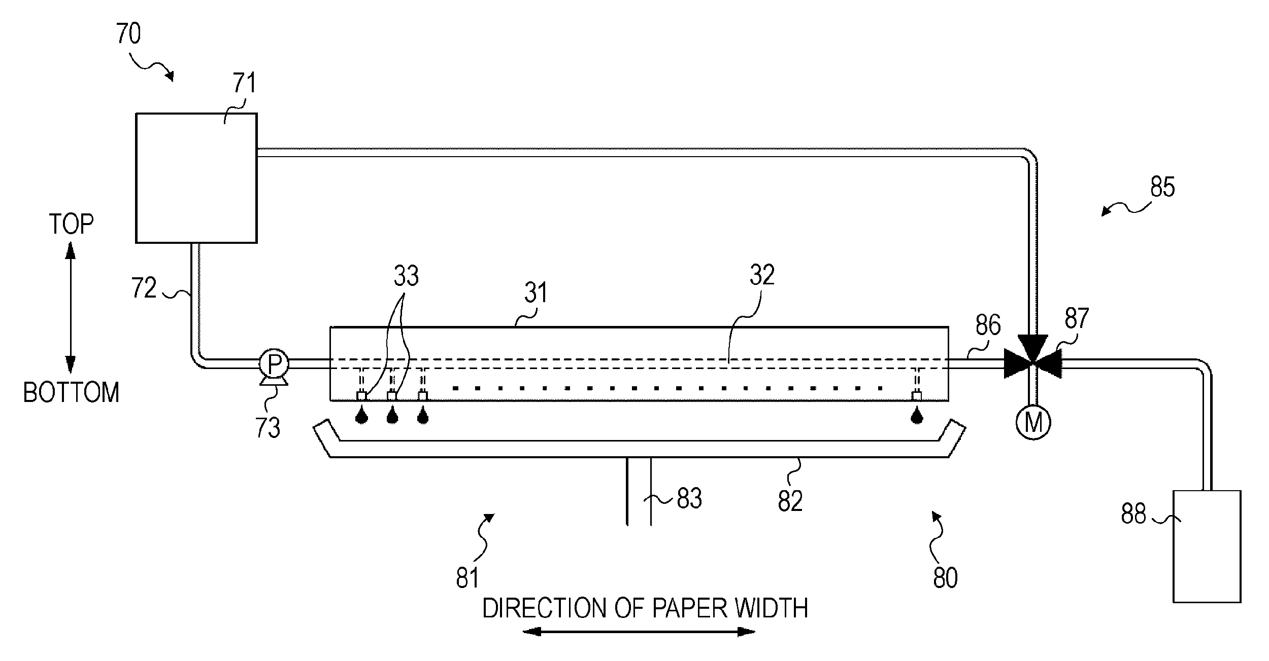
[0066]In the above embodiment (the first embodiment), the ink discharged from the head channel 32 flows through the discharge passage 86 to the waste ink tank 88 or the ink cartridge 71. As an alternative, the ink may be sent only to the waste ink tank 88 as in a second embodiment described below.

[0067]FIG. 8 is a schematic diagram of an ink supply unit 70 and an ink collection unit 80 according to the second embodiment. The second embodiment has a two-way valve 89 in place of the three-way valve 87 of the first embodiment, shown in FIGS. 4, 5, and 6. The discharge passage 86 is connected only to the waste ink tank 88 downstream from the two-way valve 89. Therefore, when the two-way valve 89 blocks the discharge passage 86, the ink discharged from the head channel 32 by the pressure from the supply pump 73 is forcibly ejected from the nozzles 33, as shown in FIG. 4. On the other hand, when the two-way valve 89 opens the discharge passage 86, the ink pressurized by the supply pump 73...

third embodiment

[0070]A third embodiment is different from the above two embodiments. The third embodiment is constructed such that the ink discharged from the head channel 32 flows through the discharge passage 86 to reach only the ink cartridge 71.

[0071]FIG. 9 is a schematic diagram of an ink supply unit 70 and an ink collection unit 80 according to the third embodiment. The third embodiment has the two-way valve 89 as in the second embodiment but does not have the waste ink tank 88. The discharge passage 86 is connected only to the ink cartridge 71 downstream from the two-way valve 89. Therefore, when the two-way valve 89 blocks the discharge passage 86, the ink discharged from the head channel 32 by the pressure from the supply pump 73 is forcibly ejected from the nozzles 33 (see FIG. 4). On the other hand, as shown in FIG. 9, when the two-way valve 89 opens the discharge passage 86, the ink pressurized by the supply pump 73 is discharged from the head channel 32 and flows through the discharge...


PUM


Abstract

A fluid ejecting apparatus including a head having a nozzle for ejecting fluid, a storing section that stores the fluid, a pressurizing section that applies pressure to the fluid so that the fluid flows from the storing section to the head, a discharge passage through which the fluid may be discharged from the head without passing through the nozzle, a valve provided in the discharge passage, a reservoir connected to the end of the discharge passage, and a circulating passage which connected to the end of the discharge passage which is connected to the storing section. The fluid ejecting apparatus has an ejection mode where the fluid is ejected from the nozzles, a discharge mode where the fluid is discharged to the reservoir, and a circulation mode where the fluid is discharged to the storing section through the circulating passage.

Description

[0001]The entire disclosure of Japanese Patent Application No. 2007-177876, filed Jun. 28, 2007 and Japanese Patent Application No. 2008-113046, filed Apr. 23, 2008 are expressly incorporated herein by reference.BACKGROUND OF THE INVENTION[0002]1. Technical Field[0003]The present invention relates to a fluid ejecting apparatus. More specifically, the present invention relates to a system and method for controlling the fluid within a fluid ejecting apparatus.[0004]2. Related Art[0005]One example of fluid ejecting apparatuses currently known in the art comprises an ink jet printer that is capable of printing on various media, such as paper, cloth, and film, by ejecting a fluid (ink) thereon. Typically, the printers are equipped with a head having a plurality of nozzles that eject the fluid, a series of channels through which the fluid is sent to the nozzles, and a storing section that stores the fluid supplied to the head. Generally, the fluid supplied from the storing section is supp...

Claims


Application Information

Patent Timeline
IPC IPC(8): B41J2/175
CPCB41J2/16526B41J2/175B41J2/1707
Inventor WATANABE, EIICHIRO
Owner SEIKO EPSON CORP
Why Eureka
Try Eureka