Apparatus For Communicating With A RFID Tag, Tape Cartridge And Tag Tape

Active Publication Date: 2009-01-01
BROTHER KOGYO KK
View PDF5 Cites 38 Cited by
  • Summary
  • Abstract
  • Description
  • Claims
  • Application Information

AI Technical Summary

Benefits of technology

[0019]A first object of the present invention is to provide an apparatus for communicating with a RFID tag, a tape cartridge and a tag tape, by making a print control based on the presence or absence of a RFID circuit element or the layout of the RFID circuit element, enabling to improve the convenience of a user (operator).
[0020]A second object of the present invention is to provide an apparatus for communicating with a RFID tag and a tag tape for use therein, by making a print control based on the presence or absence of a RFID circuit element or the layout of the RFID circuit element, enabling to produce various layout aspects of RFID labels meeting a wide range of needs of a user, and thus enabling to improve the convenience of a user (operator).
[0021]A third object of the present invention is to provide an apparatus for communicating with a RFID tag, by making a print control based on the presence or absence of a RFID circuit element or the layout of the RFID circuit element, enabling to produce a RFID label

Problems solved by technology

As a result, the label of a layout aspect a user (operator) desires cannot be produced, and thus a variety of needs as described above cannot be met.
In this case, since the layout point of the RFID circuit element in the print-receiving tape will be in concavo-convex shape, there is a possibility that e.g., the fading of a print occurs, and thus a print quality comes to be poor.
The

Method used


Image

  • Apparatus For Communicating With A RFID Tag, Tape Cartridge And Tag Tape
  • Apparatus For Communicating With A RFID Tag, Tape Cartridge And Tag Tape
  • Apparatus For Communicating With A RFID Tag, Tape Cartridge And Tag Tape

Examples


first embodiment

[0118]A first embodiment according to the present invention will be described with reference to FIGS. 1 to 25.

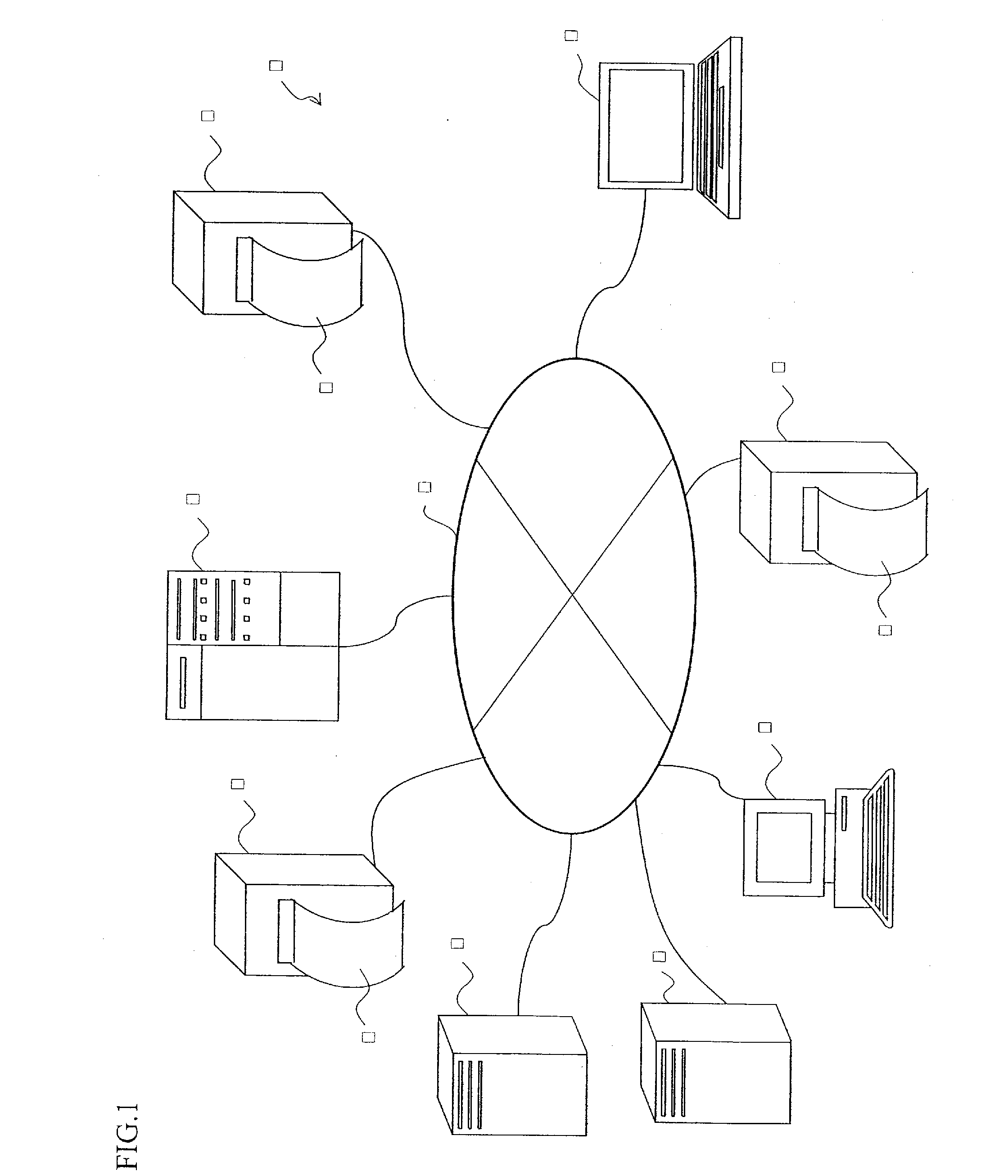
[0119]FIG. 1 is a system arrangement view illustrating a RFID tag manufacturing system to which an apparatus for communicating with a RFID tag according to this embodiment is applied. This embodiment is an embodiment in the case where the present invention is applied to a manufacturing system of a RFID tag capable of only being read (incapable of being written).

[0120]In a RFID tag manufacturing system 1 illustrated in FIG. 1, an apparatus 2 for communicating with a RFID tag according to this embodiment is connected to a route server 4, a terminal 5, a general purpose computer 6, and a plurality of information servers 7 via a wired or wireless communication line 3.

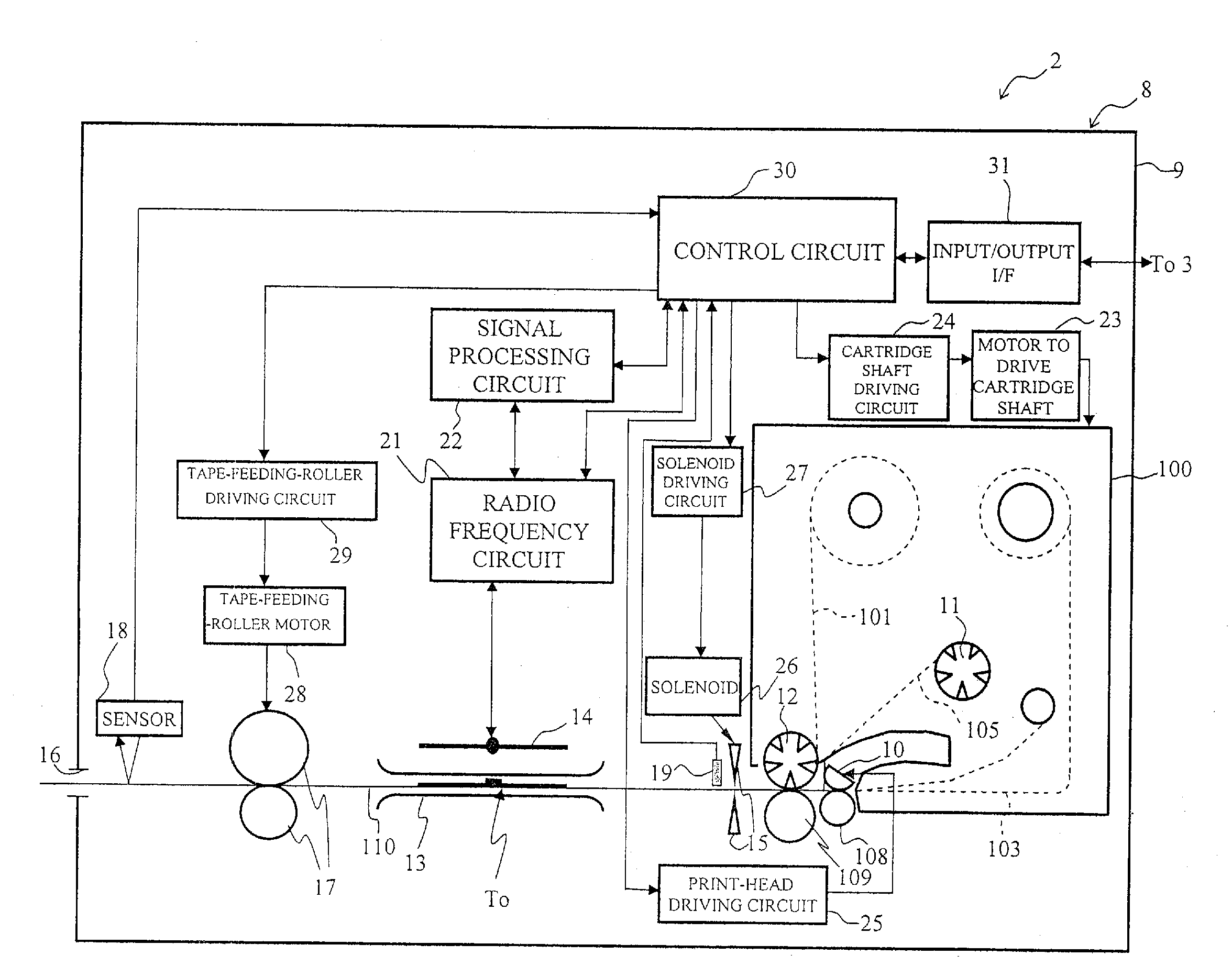
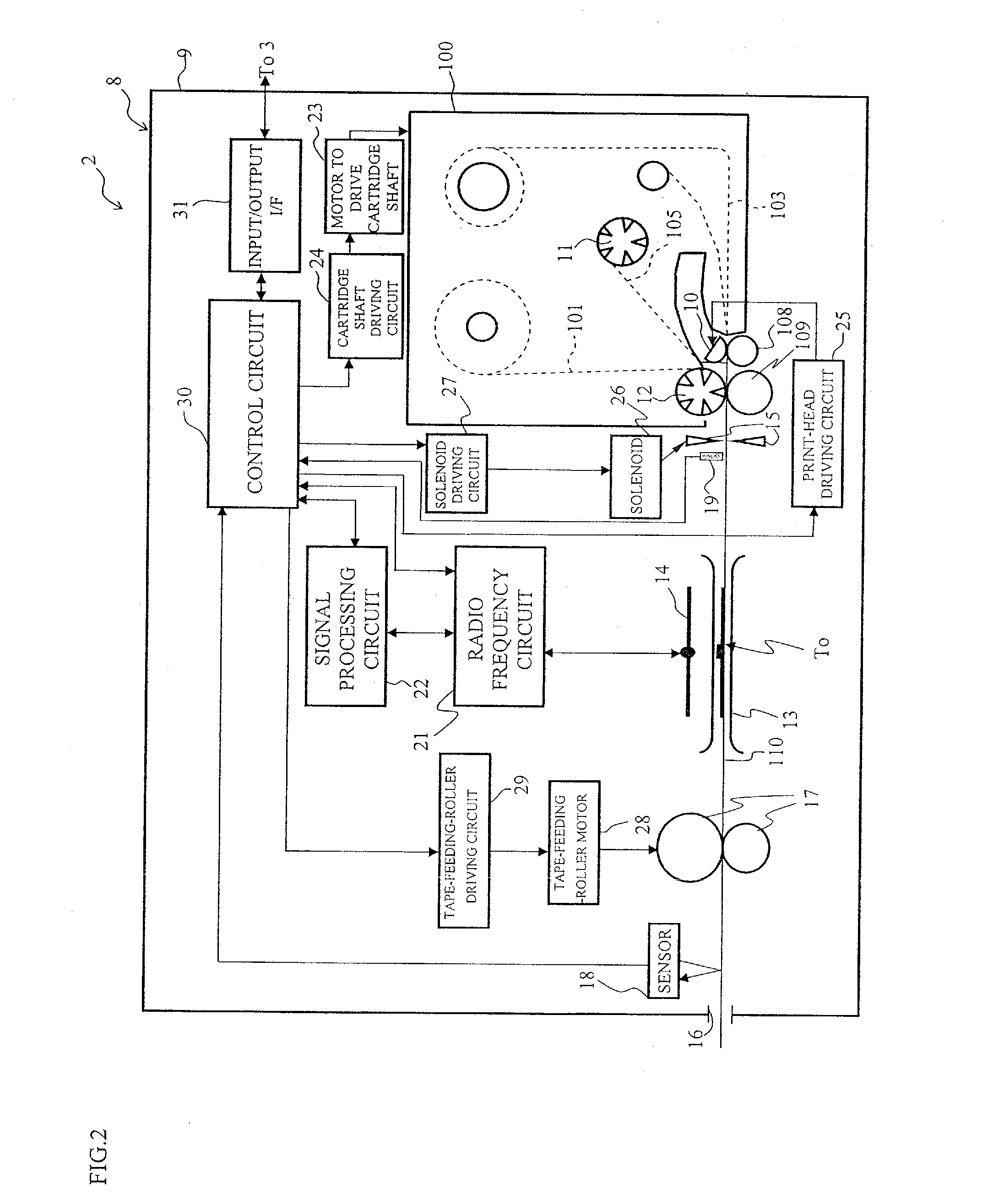
[0121]FIG. 2 is a schematic diagram illustrating a detailed structure of the above-mentioned apparatus 2 for communicating with a RFID tag.

[0122]In FIG. 2, in an apparatus main body 8 of the apparatus 2 for communic...

second embodiment

[0270]A second embodiment according to the present invention will be described with reference to FIGS. 26 to 42.

[0271]FIG. 26 is a schematic diagram illustrating a detailed structure of an apparatus 2 for communicating with a RFID tag according to this embodiment, and a drawing corresponding to FIG. 2 of the above-mentioned first embodiment. Like reference numerals refer to the same parts as those of FIG. 2, and descriptions thereof are omitted.

[0272]In FIG. 26, in the apparatus 2 for communicating with a RFID tag according to this embodiment, the photo sensor 19 is eliminated from the construction illustrated in FIG. 2, as well as there is provided a sensor (a second detecting means) 20 configured to detect layout-information of a RFID tag (information showing a layout position of a RFID circuit element To in the base tape 101. For example, a tape width, layout interval information of the RFID circuit element To and the like are included.) in a part to be detected 190 (details will...

third embodiment

[0366]A third embodiment according to the present invention will be described with reference to FIGS. 43 to 62.

[0367]FIG. 43: is a schematic diagram showing the detailed structure of an apparatus 2 for communicating with RFID tags according to the present embodiment; and corresponds to FIG. 26 and the like in the above-described second embodiment. The same parts as the first and second embodiments are represented by the same symbols and the explanations are omitted. In FIG. 43, in an apparatus 2 for communicating with RFID tags according to the present embodiment, the feeding rollers 17, the motor for the feeding roller 28, the tape-feeding-roller driving circuit 29, and the sensor 18 are omitted from the configuration shown in FIG. 26. Further, to a cartridge holder (a holder for setting a tag tape, not shown in the figure) as a recess, in the same way as the configuration shown in FIG. 25 of the above-described first embodiment, a cartridge 100′ (a cartridge for including at least...


PUM


Abstract

There are included an antenna transmitting and receiving information through a radio communication with a RFID circuit element, a signal processing circuit and a transmission portion of a radio frequency circuit configured to execute write or read of information with respect to an IC circuit part of the RFID circuit element, a tape-feeding-roller drive shaft for feeding out a base tape from a first roll, a cutter configured to cut the base tape fed out by this tape-feeding-roller drive shaft to a predetermined length to produce a RFID label, a print head making a print in a predetermined print region of the base tape, and a control circuit configured to control this print head so as to be capable of being switched between the print in a forward direction and the print in a rotation direction inverting this forward direction with respect to a predetermined print region.

Description

CROSS-REFERENCE TO RELATED APPLICATION[0001]This is a CIP application PCT / JP2006 / 308176, filed Apr. 19, 2006, which was not published under PCT article 21(2) in English and claims the benefits of Japanese Patent application No. 2005-181465 filed Jun. 22, 2005, No. 2005-121157 filed Apr. 19, 2005, No. 2005-132175 filed Apr. 28, 2005 and No. 2005-178851 filed Jun. 20, 2005.BACKGROUND OF THE INVENTION[0002]1. Field of the Invention[0003]The present invention relates to an apparatus for communicating with a RFID tag configured to produce a RFID label with which an external radio communication of information can be performed, and a tape cartridge as well as tag tape for use therein.[0004]2. Description of the Related Art[0005]There has been known a RFID (Radio Frequency Identification) system configured to execute read / write of information contactlessly between a small-sized RFID tag and a reader (reading device) / writer (writing device). A RFID circuit element provided in the RFID tag in...

Claims


Application Information

Patent Timeline
IPC IPC(8): G06F3/12H04Q5/22
CPCB41J3/4075B41J3/44G09F3/10G09F3/0294G09F3/02
Inventor NIWA, AKIHIKOIKEDO, TATSUHIROUENO, HIDEOFUNATO, NOBUHIKOTAKI, KAZUNARIOHASHI, TSUYOSHINAGAI, TAKUYAHIROTA, MITSUO
Owner BROTHER KOGYO KK
Why Eureka
Try Eureka